Continue to Site

Eng-Tips is the largest engineering community on the Internet

Intelligent Work Forums for Engineering Professionals

  • Congratulations GregLocock on being selected by the Eng-Tips community for having the most helpful posts in the forums last week. Way to Go!

Identifying a spline 2

Status
Not open for further replies.

kstopp

Mechanical
Nov 10, 2016
7
I'm trying to identify the spline that comes on a Honda CBR600RR transmission output shaft in order to produce a custom tooth sprocket for my school's FSAE team.

I have both the transmission output shaft and a new sprocket to measure, but I don't have access to measurement pins or any sort of CMM or shadowgraph to use.

It appears to be a flat root, side fit with an involute curved tooth. There are 13 teeth. Some rough measurements with a digital caliper of the output shaft gave me a major diameter of 1.160in and a minor diameter of 0.980in. However measuring across an odd diameter spline was very awkward to get the minor dia.

I've uploaded a scan of the sprocket and based on some sketches I overlaid in Solidworks I was able to come up with some measurements that are very close to an ANSI B92.1 12/24 30deg spline. However, if I switch to the metric equivalent of a B92.2M with 2.11667m, the minor diameter lines up slightly better. But I don't think metric modules come in anything other than 1.75, 2, 2.5 etc, correct?

I can't find much information for JIS splines, however I don't think there is an appropriate module available that would match my spline.

Can anyone lend a hand? Ultimately I'd love to have a dxf or something to get the custom sprocket wire EDM'd.

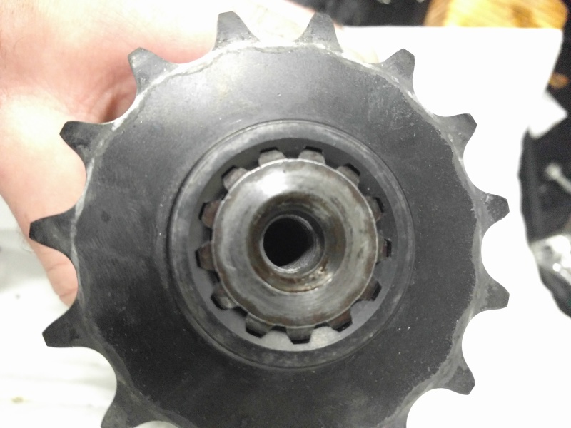
 
 http://files.engineering.com/getfile.aspx?folder=c5a690eb-df37-4e65-a30c-dc1c06c72ad2&file=Sprocket.png
Replies continue below

Recommended for you

Unless you're trying to make a tiny sprocket, you can use a composite one.

By which I don't mean plastic; I mean turn a stock sprocket's teeth off, and keep going to ~the middle depth of the hub, then bore out the hub of a stock sprocket of the the size you want to a press fit with the new splined hub core you have made, and secure the assembly with several Dutch pins, i.e., dowels pressed into reamed paraxial holes at the interface.


Mike Halloran
Pembroke Pines, FL, USA
 
Go with a Woods metal variant casting metal to make a transfer of the bore - it will fit the bore, then shrink for a while before returning to the original size, for a while. This will allow measuring the diameter. Cerrosafe is one brand name, but there are others. Density seems to be 1/3 pound per cubic inch; looks like around $40-50/pound. A rubber plug should decrease the amount required without interfering with the shrinkage. It is reusable and has other uses, so it's not a one shot-discard.

Check to make sure the expansion is per inch.

"Unlike Woodsmetal which swells upon cooling and cannot be removed from a gun chamber, Cerrosafe shrinks during the first 30 minutes of cooling and then at the end of an hour, is EXACTLY chamber size. At the end of 200 hours it will have expanded approximately .0025". This factor is well known by all toolmakers and they will take it into consideration when making dies or reamers or gauges from your cast - if you will tell them the cast is of Cerrosafe. Cerrosafe melts between 158° - 190° F. It should be melted in a clean, iron ladle. Source of heat should be removed as soon as the alloy is completely melted, at which time it is ready to pour. The solidified casting should be removed from the chamber before, or when, it cools to room temperature. If allowed to remain in the mold over an hour, it will grip the chamber walls and be difficult to remove. Clean the chamber of the rifle thoroughly, then plug the bore immediately ahead of the throat with a small rag - but not so tightly it cannot be driven out. If possible, pour the molten Cerrosafe through a small tube into the bottom of the cast, gradually removing the tube as the chamber fills. If the barrel is cold, warm it to room temperature or above before making the cast. When cooled, remove from chamber, using a rod or dowel from the muzzle end of the gun."
 
kstopp,

Mike Halloran makes a good suggestion.

Buy a new sprocket; machine off the outer rim section to about half way between the sprocket tooth roots and the hub OD; machine a new rim section disc from the appropriate steel alloy that press fits onto the modified sprocket rim OD; TIG weld (V groove) both sides of the joint using the appropriate filler alloy; stress relieve/heat treat if budget allows; fixture the part using the spline and machine the new outer rim to the correct cross section profile; machine the new sprocket tooth configuration you require using CNC mill/wire EDM/hobbing/etc; round the sprocket tooth corners and lightly polish the tooth flank surfaces.

Hope that helps.

 
Most Japanese automotive splines are as per JIS B1603-1995.
The spline which your image shows looks more like a Major Diameter Fit spline with a 20deg generating pressure angle. The standard above doesn't cover this.

There is another Japanese automotive spline that is now obsolete but still used on many parts. Parts like CV Joints, sprockets, timing gears, etc.
The standard is JIS-D-2001 and is unique as it utilises a 20deg generating pressure angle. All other involute splines are either 30deg or 45deg.
This standard also allows for a MDF (major diameter fit) to be used. You can confirm this by measuring the clearance between the major diameters of the assembled parts. If it looks like there is very little clearance (or sometimes none at all) then it's a MDF spline.
So for 13 teeth with a MDF, here are the measurements............they seem very close to yours.

Ext maj diam - 29.91 - 29.98mm
Ext min diam - 25.20mm

Int maj diam - 29.96 - 29.98mm
Int min diam - 26.00mm

BTL (base tangent length) over 3 teeth of the shaft should be close to 16.22mm.
 
I tried to get some dimensions from the scan you have sent only to find out, that the resulting accuracy is far too little to be useful. To me it looks like the spline needs to be measured to be indentified.
 
Thank you everyone for the feedback. Unfortunately the school is closed today and I can't access the pieces to check the measurements you provided. I have a photo that I took of the pieces mated together that shows a large clearance between the major diameters, which is what initially let me to believe it was a side fit. I will measure this clearance as soon as I can get access again.

IMG_20161104_152120_toqu31.jpg


What's the most appropriate method of determining the spline, if I could somehow access more advanced equipment?
 
Not being a MDF spline makes things a lot easier.

The next step to take is to measure the base pitch.
For this 2 base-tangent-length measurements are required.
In this case; the BTL across 2 teeth & 3 teeth are needed, see example below.
Also, a 3rd measurement across 4 teeth might be helpful.
Once the BP is known, then we can work out the pitch & pressure angle.


Base_Tangent_Length_Example_jasron.jpg
 
In case of a spline, the span measurement is usually possible only over one defined number of teeth, because the teeth are relatively short. A CMM measurement would save a lot of trouble.
 
gearcutter: I measured the BTL across the teeth as follows:

2 teeth: 10.20mm
3 teeth: 16.00mm
4 teeth: 21.38mm

I would say the error on these measurements is +/- 0.02mm. This was done with a digital vernier caliper, I can try to use a micrometer with the proper tips if necessary.
 
Try to find 2 pins of the same diameter, something around 3.60mm. It doesn't have to be exactly that size. The most important thing is that the diameters are the same. The shanks of twist drills are a good option.
Place the 2 pins in opposite tooth gaps (for an odd number of teeth this won't be exactly 180deg) and let us know the distance you measure when placing the callipers over the pins. Also let us know the pin size.
If you find that the pins are making contact with the root diameter, grind a small flat on the pins so as to ensure that there is clearance between the pins and the root.
 
I was able to take some measurements today as you described. I used pins that were 3.564mm, and measured 32.837mm across the two pins.

This came from imperial measurements at:

0.1404in Pin Dia
1.2928in Across Pins
 
It's increasingly looking like it's a JIS-D-2001.
We'll need to confirm some of the hub's dimensions.
Your idea of scanning the part is an excellent idea as it gives a very good representation of the scale.
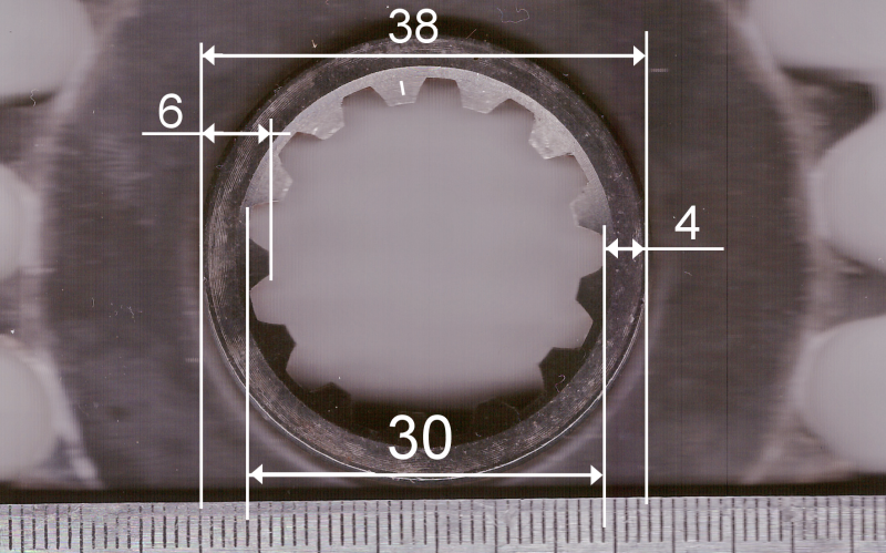
When working with odd numbers of teeth; try using a reference diameter to measure off. See the first image below. Note how I've estimated the size of the boss and then measured the radii that reference the diameters we need. This works quite well assuming that the spline profile and boss have been machined on-centre.

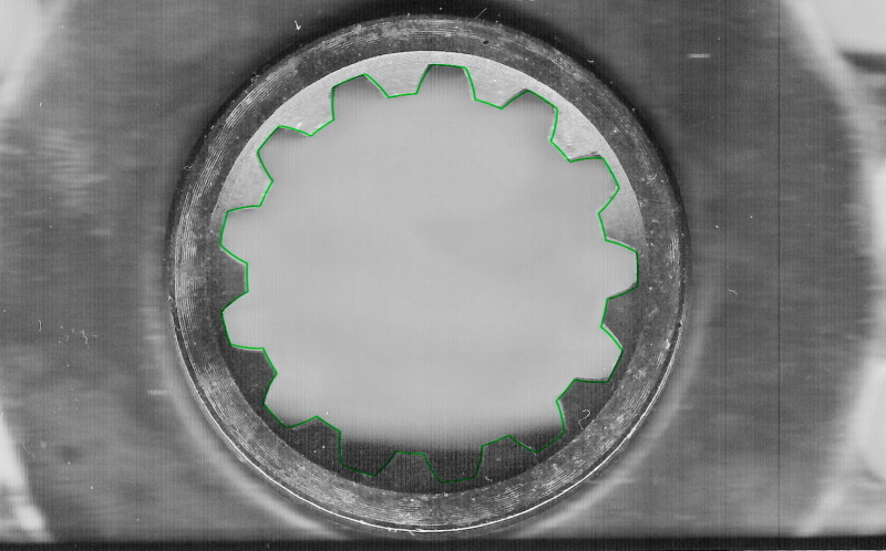
The second images shows the JIS profile overlayed (bright green line) on your scanned image. It certainly is very close.

Sprocketc_abdzri.png


Sprocketccc_dwwyyw.jpg
 
I'm reading the following:

38.47mm on the hub OD
28.20mm on from spline root to root (Sorry I forgot you asked for root to tip)
4.05mm tooth root to hub OD
6.16mm tooth tip to hub OD
 
Your spline is as per JIS-D-2001.
The type of fit (either class A,B,C or D) is controlled by the shaft's dimensions.
Data below is taken directly from the Standard.

2 module, 20deg Pressure Angle
Flat Root, Side Fit
Z = 13

Hub Dimensions
Maj diam = 30.60
Min diam = 26.00
MBP 4.00mm = 21.94 - 22.02

Shaft Dimensions
Class A
Maj diam = 29.60
Min diam = 25.20
MOP 3.60mm = 32.87 - 32.95
BTL k3 = 16.21 - 16.25
 
Cheers gearcutter, thank you on behalf of my FSAE team and myself!

Any chance you can generate DXFs of the internal spline, so I can get the sprocket wire EDM cut?
 
13502689_10154322072711204_587017891729788194_o_gn1sqk.jpg

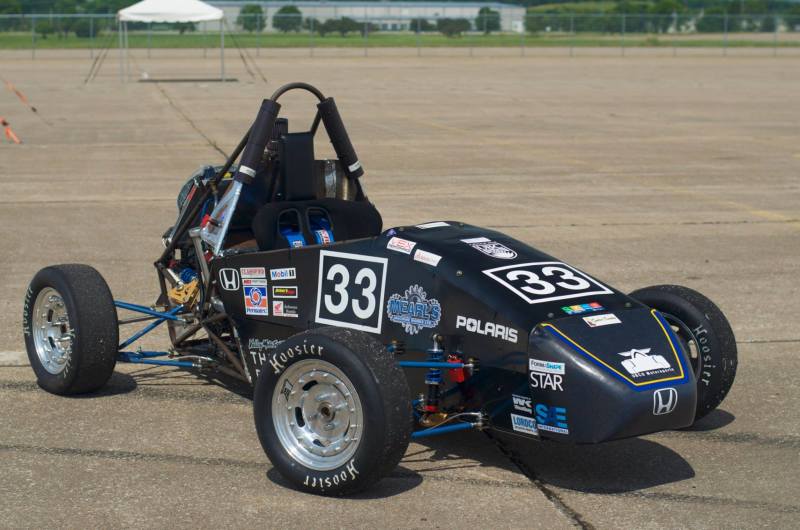
Here's the car at competition in Lincoln, Nebraska last year. This was the first year our university brought a car to competition. A very happy day for all of us.

15134429_10154601946610140_1191972097_n_qyryqi.jpg

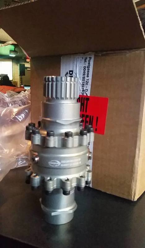
We are upgrading our rear diff this year to a Drexlar unit, saving us a lot of weight and helping us put our power down a lot better.

15153080_10154601947835140_1792918193_o_n1ukae.jpg

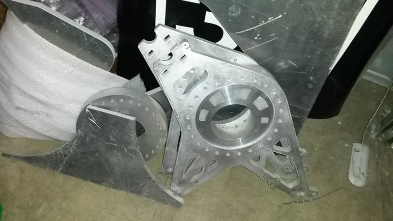
We just recently started working on our new diff and engine mounting brackets, cut on the water jet at school here. They still have a bunch more work to do.
 
Status
Not open for further replies.

Part and Inventory Search

Sponsor