Eng-Tips is the largest engineering community on the Internet

Intelligent Work Forums for Engineering Professionals

  • Congratulations waross on being selected by the Tek-Tips community for having the most helpful posts in the forums last week. Way to Go!

identifying cause of output waveform distortion on 24kW single phase generator 5

Status
Not open for further replies.

k2panman

Electrical
Jun 15, 2004
44
0
6
US
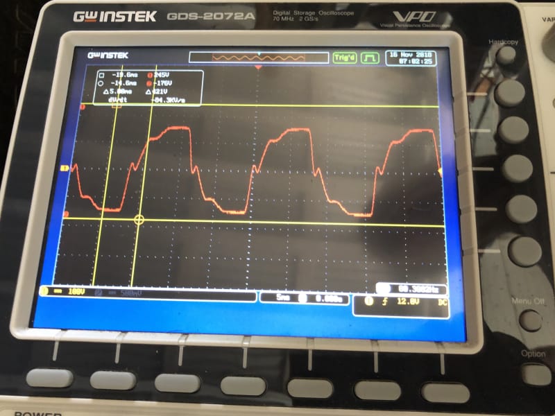
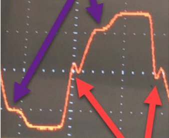
A friend has a Chinese made 24kW diesel pm 60 Hz 3 phase generator wired for single phase output (zig-zag I think). He is off grid here in Hawaii, and has used it for backup to his PV system occasionally. After he burnt up a few appliances, we looked at the output on my oscilloscope and found this distorted waveform.
scope_trace_-_output_of_David_s_generator_tjctre.png


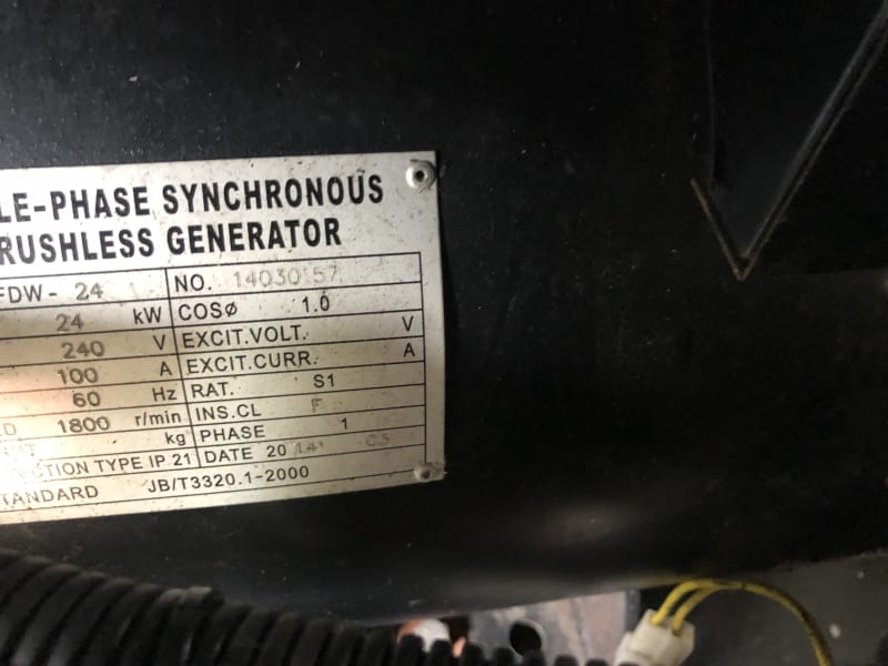
This is a brushless, self-excitated rotating field generator. The nameplate list the Chinese standard JB/T 3320.1-2000. We have replaced the AVR module with a new one with no change to the output. Any ideas on what to look at to find the problem are greatly appreciated.

K2ofKeyLargo
 
Replies continue below

Recommended for you

Rated voltage? V/div on the scope? Nameplate picture? Or at least numbers. What appliances were cooked? Why single phase?

Gunnar Englund
--------------------------------------
Half full - Half empty? I don't mind. It's what in it that counts.
 
Looks like something is saturating. Is the zig-zag connection definitely correct?

The multiple zero crossings are likely the result of a distorted load, probably quite large in relation to the machine rating. Anything electronic with an active PFC front end will struggle with that waveform, the usual result is either shutdown or smoke.
 
Here's more info and a full scope trace - Output of the generator is 120/240V single phase. The scope traces were taken with NO LOAD, but we connected a resistance heater to the generator and the trace had the same distorted waveform. The scope was just connected across the 240V output terminals of the generator, scope was powered off another generator and isolated.

IMG_1067_qplmy1.jpg


The scope shows a Vp-p of 421V - not sure why the scope trace values in the upper left corner are showing +245V -176V, but I thought it was symmetrical about zero.

ScottyUK, I don't know if the connections are correct - maybe not. I didn't look at the connections as we would have had to remove some shrouds, but we will definitely take a look. The company who sold the unit sent a "technician" out to look at it a while ago, and declared everything ok on the generator, but he didn't even connect an oscilloscope to it.

Here's most of the nameplate (must have been hard to see - covered by a shroud I think:

IMG_1068_nhpuf4.jpg


There isn't a company name on the nameplate.

Checking again, I found out that a washing machine and a microwave both gave "error codes" and would not run, but they did not burn up. The appliances run fine off the Outback PV system running FXR3048 inverters with a 48VDC battery bank, or off a Honda 3000W or Honda 2000W generators, which are pure sine wave output. He's running single phase because it is a house - all single phase loads.

K2ofKeyLargo but now Hawai'i
 
This is Waross or Catserveng territory.

But I have seen lights go dark when switching load on and then go extremely light when switching load of and usi gensets. The AVR isn't terribly fast so the high voltage when switching off can remain for a few seconds. That may be enough to kill small appliances.

If you take timebase to 1 s/div, and set the trigger to around 10% above voltage peak and then switch load off, you may be able to see if that is true.

If so, it may be a problem doing anything about it. A magnetic stabiliser could work. But they are sensitive to frequency variations.

Gunnar Englund
--------------------------------------
Half full - Half empty? I don't mind. It's what in it that counts.
 
So I have one question right off, you state in original post this is supposed to be a 3 phase generator, nameplate says a single phase, have you positively identified how you have this generator connected?

Have you taken your scope and looked at the AVR field output? Are you able to connect a current probe and look at a trace of the current and voltage against a resistive load? That's a 2 channel scope, right?

You said you took the scope readings at line to line 240VAC right? Have you taken any readings L1 to N and L2 to N, and N to Gnd? The difference between the positive and negative voltages makes me wonder if your bonding/grounding is correct. Don't think its the whole problem but many times its a combination of factors making things not work right.

I dug thru a bunch of old power metering and scope traces for smaller generators, I don't think this is a rectifier or exciter issue, based off what reference info I have. The waveform distortion seems pretty symmetrical cycle to cycle, and the spike at each side of the voltage waveform at the zero crossing is pretty odd. Only thing I could find in all my old stuff that had a similar appearance was a problem we found with a larger unit (about 600 ekw) that had a core iron issue.

How about some history, did this generator originally work ok with this system and now has a problem, or never worked right at all?

Hope that helps, MikeL.
 
Some comparison scope traces from L1 to N and from L2 to N may be helpful.
If you can see the leads:
A three phase set will have 10 or 12 leads.
A single phase set will have 4 leads.
A three phase set will have six poles. The stator windings will resemble the windings in an 1760 RPM or 1460 RPM induction motor.
A single phase set will have four poles. The stator windings will resemble the run windings of a single phase 1760 RPM or 1460 RPM single phase motor, if you ignore the starting winding.
The two most common ways to derive single phase from a three phase set are the Zig-Zag connection and the Double Delta connection.
Checking from each line to neutral with a simple multi-meter will show equal resistances for a Double Delta connection and a 2:1 ratio with a Zig-Zag connection.
Do you have the AVR connected to 120 Volts or to 240 Volts.
A 240 Volt AVR connected to 120 Volts may push the windings into saturation as it tries to raise the 120 Volt winding to 240 Volts and may give strange waveforms. It will also give overvoltage on the 240 Volt leads.
Also there may be current limiting issues with the AVR if it is connected to a low voltage.

Bill
--------------------
"Why not the best?"
Jimmy Carter
 
Back to basics: connect it as a straight 3-phase 4-wire machine. Bring the field up gently from an external variable DC supply. You should get a nice balanced set of three sinusoids. Bring it up to rated voltage, check the waveforms are still healthy. Substitute the AVR back into the field and check again. Verify that your AVR sensing leads are in the right place if you're reconfiguring from 1-phase to 3-phase.
 
Good idea using external excitation Scotty.
I would try that on the single phase connection and only go to the trouble of changing connections if the single phase test is inconclusive.

Bill
--------------------
"Why not the best?"
Jimmy Carter
 
Thank you all for the ideas and suggestions.

I can do some further checks, we'll have to disassemble and hunt for these connections. We don't have a wiring diagram for the generator, and I've not done any work on generators in the past, but I'll certainly dig into this. Nothing on the AVR is labeled, and the wiring is behind panels, and I'll try to draw out a sketch of the connections.

I asked my friends for more info on their experience with the generator - here's the correct info: The generator was configured at the factory for single phase 120/240V output - shipped to him here in Hawaii from Arizona. The "factory technician" came on site and declared that the generator was all connected correctly and output was fine, and that the problem was not in the generator.

The house primarily runs off the PV and battery system with the Outback Power inverters/charger controllers. (Outback is top of the line off grid equipment - lots of homes use Outback equipment here, and they have great support). Everything in the house runs fine on the Outback system.

The generator has been connected to the house for maybe 6 years. They have powered the house many times over the running 120V lights and appliances. There are no 240V loads on the house - the stove, oven, clothes dryer are all propane, water heated with solar. They haven't burnt up anything, just the washing machine and microwave electronics have prevented these appliances from running and displayed error codes.

I do have a two channel scope, but no current probe. If we need a current probe to find the problem, I can get one - I hope I can find one that works for $100 and not have to spend $500 for one.

I will go tear into this further and get back with what I find. Thanks again Skoggsgura and Catserveng.


K2ofKeyLargo but now Hawai'i
 
You can scope L1 to N and L2 to N without changing connections.
Then excite to brush-less exciter field with a DC power supply as Scotty suggested and scope again.
Disconnect the AVR completely from the exciter field when using the DC power supply.
It is best to avoid disconnecting the stator leads if at all possible. With a 12 lead machine there are too many possibilities for a mistake.
Confusing a 6 with a 9 is easy to do and is a sure way to liberate the smoke.
If this is a three phase machine factory configured for single phase then some connections may be buried.
There are two basic methods of producing a single phase machine from a three phase machine.
Taking a 30 KVA three phase machine as an example:
Method 1, A three phase 30 KVA machine would be reconnected as a single phase 20 KVA machine with the engine left unchanged.
Method 2, A three phase 30 KVA machine would be reconnected as a single phase 20 KVA machine and an engine with a capacity of 20 kW for unity PF or or 16 kW for a 0.8 PF machine.
Method 2 is never intended to be used as a three phase machine and some connections may be buried.

Bill
--------------------
"Why not the best?"
Jimmy Carter
 
Ok, great. I have a lot of things to check. I will need to aquire a DC power supply - don't have one since I left the electronics business, but as I've come across the need for one several times, it is a good time to get one. What would the typical field winding current and voltage be for this machine? I understand how that is going to work, but have never done this. Good to take the AVR out of the system for test. I will also have to figure out the connections to the AVR. I am going from memory - I think there are 5 leads on the AVR. Can anyone point me to a typical wiring diagram for the AVR on this machine?


K2ofKeyLargo but now Hawai'i
 
I wouldn't care too much about the waveform.

Going back to your first post, the problem wasn't at all the waveform but rather that some appliances were not feeling well (died, actually). That happens over and over again and often because of a sluggish AVR so voltage overshoots when heavy loads are switched off.

Quite often, looking too deep into a problem leads to false conclusions. An "engineering field day" is always interesting and often challenging. But if you are going to invest more time - and some money - I recommend that you do the test that I mentioned in my 17 Dec 18 21:16 post. Or perhaps you did? What did you find?

The appliances that got killed, what power rating were they? Some inverters and gensets carry warning texts about this saying things like "Don't use for small power supplies or charging devices". That warning may very well be valid for larger devices as well. The name-plate says 24 kW and 1% of that is 240 W. I would be very careful with loads under a few percent of generator rated power.

Instead of scope trace, a simple incandescent lamp (if you can find one today) works well as an overvoltage indicator. Connect it to the running generator, load it as much as you can and then switch off most of the load. If the lamp goes very bright for anything like a tenth to several seconds, then you have the answer.

It is a simple test and I recommend that you do that first. It is a short-cut that avoids a lot of misinterpretations and confusion.


Gunnar Englund
--------------------------------------
Half full - Half empty? I don't mind. It's what in it that counts.
 
k2panman,

With no load you'll probably raise rated voltage with about 12V and less than an amp. A lab PSU with 30V / 2A output is what I'd buy as a versatile general-purpose supply.
 
Scotty said:
With no load you'll probably raise rated voltage with about 12V and less than an amp.
Agreed.
The voltage may raise to approximately 24 Volts when loaded.

Bill
--------------------
"Why not the best?"
Jimmy Carter
 
Ok thanks. Found a 30V 10A chinese made power supply on Amazon, have it on order. I'll get over there after Christmas and do some more testing. I really appreciate all the help guys! Aloha and Mele Kilikimaka (Merry Christmas)!

Keith

K2ofKeyLargo but now Hawai'i
 
Status
Not open for further replies.
Back
Top