I'm trying to figure why ETAP gives a transformer damage curve with a huge difference under ANSI Std and IEC Std. If you have another source it would be great.
Scotty, equivalent IEEE standard to IEC 60076-7-2018 is C57.91-2011 ie Transformer loading guide; These covers -extent of permissible over loading. ageing rates, time constants, oil and winding temperature rises during transient loading etc, etc. C57.109-2018 " Guide for liquid immersed transformers through fault current duration" gives a series of graphs connecting times rated currents( ie fault currents) to permissible (or withstand) duration in seconds for different categories of distribution transformers. I found this popular in US and could not find anything equivalent in IEC world.
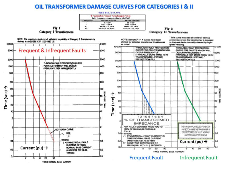
The IEEE Standards C57.109 and C57.12.59 cover SC Withstand Capability TCC damage characteristics for oil and dry-type transformers respectively. For Illustration, see below a typical transformer damage curve The concept of damage curve is not considered in the IEC.
IEC 60076-5 ed3.0-2006 Power Transformers-Ability to withstand short circuit do give the calculations for thermal withstand capability with short circuit currents. (Clause 4.1.5) IEC gives a maximum permissible average winding temperature of 250 C for copper wound, oil immersed transformers during the fault current flow. So you can estimate the time to reach this temperature for various values of fault current. But transformers engineers are convinced that failure from short circuit currents will occur during the first or second cycle due to dynamic forces rather than thermal overheating of windings. This is true esp with medium and large power transformers. That may be the reason IEEE also gives the damage curves only for distribution transformers where source impedances will be rather high. Then the fault current will be moderate and may take some time for the fuses to clear the fault. In such cases thermal withstand capability may be relevant.