Continue to Site

Eng-Tips is the largest engineering community on the Internet

Intelligent Work Forums for Engineering Professionals

  • Congratulations SDETERS on being selected by the Eng-Tips community for having the most helpful posts in the forums last week. Way to Go!

I'm designing a steel box girder. Bearing Stiffeners. I want to modify the Bearing Stiffeners.

neostark

Civil/Environmental
Mar 24, 2025
1
1742884723342.png
1742889940812.png
1742889733080.png
1742884768289.png
1742884798265.png


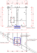
In the first figure, due to special circumstances, the position of the bridge support needs to be moved by 250 mm, as shown in the figure, and the center of the bearing reinforcement does not match the center of the bridge support.

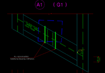
The second drawing shows an overlap of the additional bearing stiffeners, the top flange, and the bridge support, which are not centered.

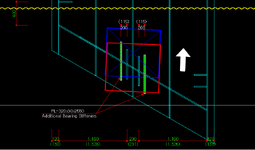
The third drawing shows an overlap of the additional bearing stiffeners, the lower flange, and the bridge abutment, which are not centered.

Would installing these additional bearing stiffeners be enough to fix the problem?

If not, how should I modify the bearing reinforcement, any suggestions would be appreciated.

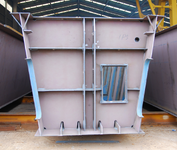
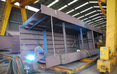
The maximum load at the center of the bridge supports is DEAD LOAD (4200KN), LIVE LOAD (1545KN). (The box in the drawing is the short span bridge we are currently designing and the photo is another bridge of similar format)
 
Last edited:
Replies continue below

Recommended for you

I don't believe that the additional stiffeners you show substantially address the shifted bearing location. I would want them to extend much further (400mm?) toward midspan, to better capture the extents of the bearing reaction. (As mentioned before, somewhat like an inverted steel corbel).

You'll have a thrust to resolve which will have to be accommodated in your girder (but if simple span as indicated, opposite to the DL stresses, which is good in a global sense).
 

Part and Inventory Search

Sponsor