Eng-Tips is the largest engineering community on the Internet

Intelligent Work Forums for Engineering Professionals

  • Congratulations waross on being selected by the Tek-Tips community for having the most helpful posts in the forums last week. Way to Go!

[img https://res.cloudinary.com/eng 1

Status
Not open for further replies.

Lucast

Structural
Aug 1, 2023
1
0
0
CA
Capture_edxha7.png


Hi guys!
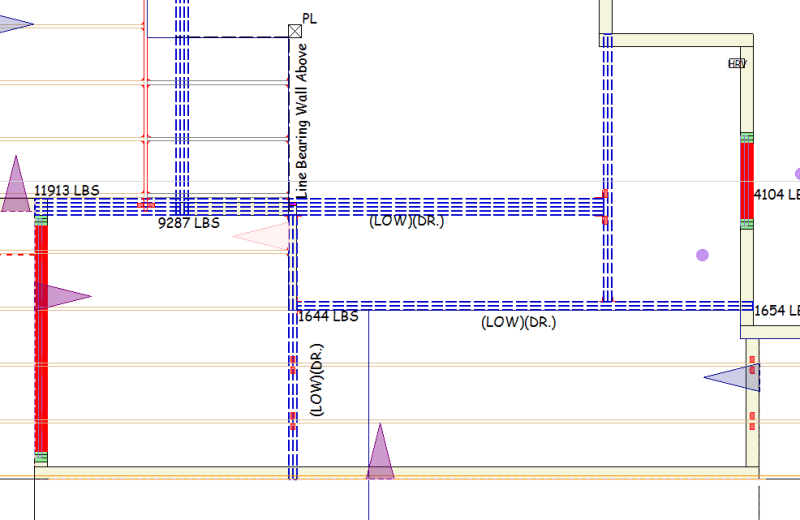
I have issue with this model. It show error circular loading and i can't run structure. I checked the error and it stated that " this member is included in a circular load path which create an indeterminate structure". Member cannot be analyzed or designed. Indeterminate structure should be a stable structure. Can anyone guide me how to calculate manually this situation or explain to me ? Thanks.
 
Replies continue below

Recommended for you

Not only is this a pain to calculate, it will be very difficult to build. Your best bet is to run one of those beams all the way to a bearing wall. I'd start with the one one that runs plan N/S on the right side, coming off the corner. Take that one all the way down to the bearing wall at the bottom of the plan view.
 
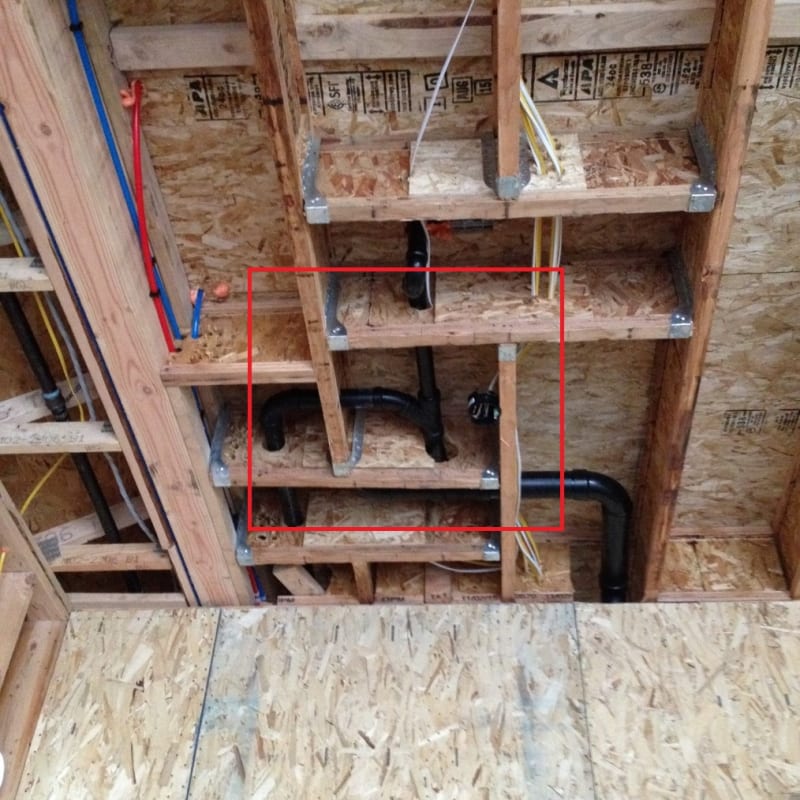
Ah, the classic circular framing problem. Take a look at the photo below, area circled in red. Notice how each piece frames into the next, and then the next, each piece is supporting the next piece in a circle, which means the load builds upon itself and has nowhere to go, this is what the software is indicating with the note about circular load path. One of the beams shown in the middle of your photo needs to be taken to a vertical support, either a column, or the beam needs to terminate on a structural wall line.

Picture11_fzcd8t.jpg
 
Some fancy folks do this reciprocal framing thing on purpose despite the erection complications and vibration performance becoming a messed up Bessel function or something. Nobody practical of course.

One way to tackle it would be via iteration:

1) Pick one beam end framing out the reciprocal ring and support it from a faux post instead of the supporting beam.

2) Run the model and get the reaction on the faux post.

3) Apply the faux post reaction to the beam that will really take reaction in place of the faux post.

4) Repeat the process until the faux post reaction is no longer increasing meaningfully and call that your solution.

Interestingly, this way of modeling the situation probably resembles how you'll have to build the thing: using at least one temporary post.

C01_c1lbhd.png
 
ChorasDen said:
...which means the load builds upon itself and has nowhere to go..

That's not quite right. The load does have somewhere to go.

One, useful way to visualize the behavior is as that of a moment splice between the pairs of framing that are parallel.

Theory aside, I would definitely seek to eliminate the reciprocal condition for this, rather pedestrian, application.
 
Kootk said:
That's not quite right. The load does have somewhere to go.

I suppose we could argue the semantics of this one, but in the context of the OP, this is a first time poster that is/was struggling to understand the meaning of the software error produced. As shown in the photo I included, yes, certainly these situations can work, but in the context for someone like the OP, my thought was that it might be better to discuss why we shouldn't try and model this situation, but should redesign the structure to ensure static equilibrium is achieved for our design members.
 
Status
Not open for further replies.
Back
Top