Continue to Site

Eng-Tips is the largest engineering community on the Internet

Intelligent Work Forums for Engineering Professionals

  • Congratulations SSS148 on being selected by the Eng-Tips community for having the most helpful posts in the forums last week. Way to Go!

Impact Force / Maximum Plastic Deformation on Cantilever Beam 4

Status
Not open for further replies.

Pengy

Structural
Dec 19, 2019
3
Let's say you have a 10' cantilevered beam with an ultimate moment capacity (not design moment @ yield, but capacity @ ultimate stress) of 200 k-ft. Is there an approach to find what the approx. total deflection (elastic+plastic) would be at the end of the cantilever if the point load resulting in the ultimate moment was placed @ some point along the beam (i.e. total deflection with 20k load @ end of cantilever, or total deflection with 40k load @ midpoint of cantilever)?

Ultimately I'm trying to determine how much a freestanding post could deflect in a collision (with the impacting item assuming to have a rigid body with no deformation) to determine the potential impact force.

 
Replies continue below

Recommended for you

My first pass at this would be to assume once the post yields at its base it's effectively pinned, and then figure out how much rotation at the base can occur before rupture.
 
I think that it's not simply pinned after the post yields, I think it can transfer a relatively constant moment if it's ductile enough.

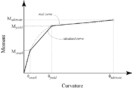
If the beam is RC (and it's probably similar if it's steel) you can find a curvature at failure, curvature at yield and curvature at cracking moment. Those 3 points determine a moment-curvature diagram. Behaviour is practically linear in between those points.
Different-States-on-Moment-Curvature-Curve_r6gyxu.png


This can easily be done with excel, matlab... and then for any moment you can determine a curvature. You can do this for a number of points along the beam. From the curvature distribution you could get rotations with numerical integration (also in excel, also an easy task) and then integrating again, you can get deflection.

I think this should give you a good estimation, but maybe I'm missing something.
 
You're getting into non-linear, inelastic analysis. It can get a bit hairy. Here's a thesis on the topic - essentially exactly what you're looking for, I think.

You may want to think about a different approach, or at least a modified one. It may be beneficial to determine the maximum allowable deflection. The true point of fixity is likely going to be at the column/foundation intersection (or thereabouts), and this will be where maximum curvature occurs. So, if you have an SUV colliding with this barrier, the point of contact is going to be 18-24" above the ground. At what point does the slope of the column at this point transition from a barrier to a ramp? Sure, it could keep deflecting, but only if the force vector rotates to continue to align itself with the axis of your column. Probably unlikely.

Of course this could have nothing to do with vehicle impacts, but the situation could apply to other scenarios, too. Just food for thought.
 
if you develop the ultimate moment at the base of the post, ie a plastic hinge, how far does the hinge rotate under the load ?

since you're considering a collision, I think you need to consider time (as the applied force is a function of time). Since the "momentary" force is creating a "momentary" plastic hinge at the base, I'd expect the tip of the post would deflect "a lot"

since you're considering a collision, don't you have to work from the vehicle (weighing say 1 ton), travelling at (say) 30mph impacting your post. How the vehicle decelerates will impact the deflection of the post.

another day in paradise, or is paradise one day closer ?
 
One simplified approach is to take the kinetic energy of the impacting body, and set it equal to the strain energy absorbed by the post. You can back-calculate the deflection of the post from the equations of beam strain energy under bending load. The equations would be piece-wise and vary according to the softening stiffness of the post as it yields. In other words, the total strain energy absorbed is the area under the force-displacement curve (if you used the tri-linear model that hardbutmild suggested, the strain energy absorbed by the post would "fill" the area under that tr-linear curve until the kinetic energy "ran out").

But this approach is simplified and doesn't take into account dynamic effects. This can be partially accounted for by applying strain-rate dependent material properties to the post.
 
This is similar to blast design where a numerical integration is used to find the ultimate deflection based on the equation of motion. The integration includes the resistance in the elastic range and then the integration continues with the equation adjusted as the beam goes into the plastic range. I think you need to develop the equations and do a time-step integration. This type of numerical integration is shown in some dynamics textbooks.
 
Don't forget in real world practice, strength of the foundation will play a key role in the analysis.
 
Thanks all. This is a bit of a unique situation where it will be a quite tall post with a VERY heavy vehicle impacting at low speed at any point (above say 4') along the cantilevered member.

I'm trying to come up with a reasonable approach for the design of these members and their foundations. I am planning on having a much heavier sleeved connection into the concrete with many feet of embedment. I'm trying to ensure the cantilevered member will be the limiting factor and the sleeved concrete connection will have at least 2x the capacity of the post @ ultimate (so the bollards can be removed and replaced when damaged).

 
I'm really curious now - what kind of vehicle is capable of changing its height from 4 to 10 feet, and is also extremely heavy?
 
A 72000kg capacity forklift of course!
 
If this is a safety/operation guard, which can be replaced as frequent as the condition dictates, then don't over think, just estimate the maximum force, get soil report, and follow foundation textbook, design it as soldier beam.
 
Ah. Makes sense. So, yeah - essentially non-deformable body striking your bollard.

 
a front end loader ?

another day in paradise, or is paradise one day closer ?
 
Another cheap and easy solution is to provide barrier wall to limit the movement of vehicle wheels.
 
Pengy:
How far can the tip of this 10’ canti. (bollards) move before it hits, starts harming other important structure? Is this part of the question/issue? Is there a predominant range of direction for these impact loadings? If the load can hit anyplace from about 4’ to 9’ in elev., it must be the load (different loads) which is hitting the post, because the hard points on the forklift wouldn’t change that much, except for the forks, on a direct frontal impact. Look at some good Structural textbooks on the development of Plastic Design in Steel, there are some fairly simple methods of approximating the curvature (slope, angle change) during the development of a plastic hinge. Above that region/elev. the deformation (slope, curvature) will be elastic, and should lead to a M/Φ diag. essential as hardbutmild has shown, for a load applied at any given elev. on a specific post. Watch out for buckling, which prevents the plastic hinge from fully forming; and note, that as the plastic hinge develops, it takes very little added load to significantly increase the rotation. Maybe you should take a look at docking/ship fenders and the like. They take very large impact loads, and absorb very large impact energies without yielding and destroying their supporting structures. There might be some ideas there which would lead to a clever solution, short of replacing bollards once a month.
 
Just curios, what follows when/after plastic hinge formed in structurally determined structure?

My understanding, docking and ship fenders are usually installed on pier/sturdy concrete structure with impact absorber, such as elastomeric pad.
 
The usual assumption when designing for fully plastic moment is that deflections are unlimited and you do a work equation to get the rotation. This may mean you have to design the beam so that it can actually rotate as much as necessary. The nearest analogy I know of is the crush design in the front end of cars, where hinges are encouraged to form in various places.

Cheers

Greg Locock


New here? Try reading these, they might help FAQ731-376
 
I'll go out on a limb and try to put some math to the problem. I haven't done this type of thing in a while, so feel free to correct me if I'm off base.

This example is based on load at the end of the post, just to make the math a bit simpler.
 
 https://files.engineering.com/getfile.aspx?folder=b8d19971-b4f2-4813-8fdf-e4b0e27c72f9&file=Scan.pdf
[b said:
PLASTIC BEHAVIOR OF A SIMPLE BEAM[/b] (UKY literature notes)

If a load P at the mid-span of a simple beam is increased until the maximum increased until the maximum mid-span moment reaches the fully plastic moment Mp, a plastic hinge is formed at this section and collapse will occur under any further load increase. Since this structure is statically determinate, the collapse load PC can easily be calculated to give Pc=4Mp/L.

I couldn't find anything similar for cantilever beam though.
 
Status
Not open for further replies.

Part and Inventory Search

Sponsor