Eng-Tips is the largest engineering community on the Internet

Intelligent Work Forums for Engineering Professionals

  • Congratulations waross on being selected by the Tek-Tips community for having the most helpful posts in the forums last week. Way to Go!

Impact hammer test - Modal Parameters Extraction from multiple FRFs

Status
Not open for further replies.

E2015

Civil/Environmental
Apr 20, 2015
22
0
0
IE
I have done an impact test on a railway sleeper which was embedded into railway ballast.
I did impacts at 11 points along the sleeper, and I have gathered acceleration for each of the impacts at 11 points of the sleeper, i.e. I had 11 impact/reference points and 11 response points (accelerometers).

For each impact point I have obtained eleven FRFs. So for one sleeper tested I am dealing with 121 FRF curves.

I need some advice how to proceed in getting the modal parameters. To be honest, I am pretty stuck at this steps for weeks :(

At the moment I am dealing with RFP technique for modal parameters extraction. I've found a very useful Matlab code online on Mathworks website.
The thing is I got some strange numbers while doing the fitting, e.g. negative damping ratios even though the fit looks almost perfect. This is one of the major problems now.

I admit, my data is not perfect all, but I should get something from it, because I see highly damped peaks. Also plotting the imaginary FRF along the sleeper, there are first four modes visible (up to 670 Hz). Individual FRFs are somehow similar, with almost same locations of peaks in the frequency range of interest.

I don't know am I on the right track. I know that RFP is an old technique, but for me the time is the biggest problem because I don't have it and the deadline is around the corner. Also, I don't have available any of the software that will do all the hard work for me.

So, I just want an advice of an experienced person, how to proceed. How can I take into account all 121 FRFs and at the end get the final experimental frequencies, mode shapes and damping ratio (if possible)?

Many thanks in advance,

Emina

Emina B.
 
Replies continue below

Recommended for you

I've never heard of anybody doing the full matrix of reference and response points, wow you are going to have the most robust and/or confusing data set ever!

First thing you should do is check reciprocity, ie that response at point 11 to an impact at 1 (call this H1_11) is the same as H11_1 and so on. if it isn't then all your hard work was in vain.

If you could post one of your FRFs (as numbers, not just a graph of magnitude and phase vs frequency, preferably )then it might make things easier.

One big issue is how well damped the modes are. If they are heavily damped then it is more difficult to analyse. negative damping ratios are not possible in a passive system, so far as I know.

In my opinion the most robust approach for a beginner is circle fitting, not curve fitting p23 here . This takes all the magic out of the process and forces you, the analyst, to make some hard decisions and look at your data. It is also the most aesthetically pleasing method. This gives you a phase and amplitude for each peak. You then have to decide on the global parameters, damping and frequency, for each mode. You can estimate damping and frequency by looking at a circle plot, or you can use your extracted amplitude and phase, build an MDOF model of each FRF, and vary the damping until you get the best fit.

Circle fitting may sound time consuming, but if your reciprocity comparison worked then you only need to do it for one row or column of your test matrix, ie H1...11_1 or whatever. I've done it for much bigger surveys than yours, once you've got the script set up it is quick.

There are many gotchas with circle fitting but at least you have looked at the data.


Cheers

Greg Locock


New here? Try reading these, they might help FAQ731-376
 
Hi Emina,

If I were in your shoes, I'll try to first curve fit FRF data created from a simple 3DOF system that resembles your test data (high damping, approximately similar frequency spacing). Practicing various curve fitting techniques with known answers would help you work through any bugs. When approaching your own test data, try different curve fitters and see if the results are similar.

If you can, sit down with someone who is experienced in modal curve fitting to share your approach and results. I learned a lot that way.

p/s: I've not tried it myself but here's another Matlab toolbox which has a few curve fitting functions.


Good luck,
Jason
 
Thank you Greg for your reply.

I am doing the modal analysis for the first time, so I am not experienced in the testing itself but I am giving my best to find a way how to deal with Modal Analysis for my application. But getting the full matrix is leading to more confusing data set I must admit.

Is there an indicator that I could use as a quality check of each set of the FRFs? So I have 11 sets and each set is containing 11 FRFs, how can I choose the best set of FRFs for my structure. I have read about Principal Response Function, can this be helpful?

I have attached also an example of 11 complex FRF for one impact. Link

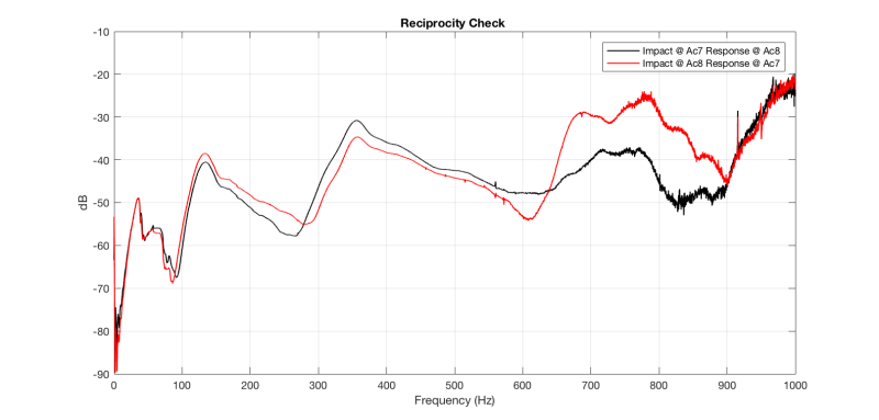
I have attached a picture of the reciprocity check as well.
Reciprocity_Check_chavzi.png

The plot is shown until 1000Hz because I am interested in those frequencies, but it usually goes up to 2.5kHz.
Mostly all the other reciprocity checks for other DOf look similar.
In your opinion can I accept a reciprocity like shown on the Figure even though the curves are not overlapping?

Thanks for the ppt, I've seen it but for the RFP. Anyway, it has a detailed explanation of circle fit method, so I might start looking at that since I can not find my way with the RFP.

Regards,


Emina B.
 
Reciprocity - Nice clean data up to 600 Hz, although a 4 dB mismatch at 360 Hz indicates trouble ahead. Your data above 700 Hz is too noisy to be of much use, and the reciprocity is lousy. if it's all you have then you may just have to suck it up and use it.

Download - many email/web/AV systems hate the .mat extension as it is related to virus or malware. We routinely rename them to .txt and warn the users.

The FRFs share the same problems, above 600 Hz the data is not usable. looking at the driving point H7_7 the phase is all on one side of zero, which is good, but again above 600 hz it wanders off into fairy land.

I'll have a better look next week

Cheers

Greg Locock


New here? Try reading these, they might help FAQ731-376
 
OK, I think I've got the deltaF right, (ie 2500/16385)

frf_byetla.jpg


So you've got a mode at 35 Hz ish, something nasty at 60, a pair of close coupled modes at 130 Hz, something nasty at 270, two close coupled modes at 360, and something nasty at 420 and 480.

The something nasty could be resonances in directions other than what you have measured, or torsionals.

Cheers

Greg Locock


New here? Try reading these, they might help FAQ731-376
 
Thank you Jason for the advice. (I don't know why I haven't seen your answer before.)

At the moment I am the only one in my department trying to work on modal analysis, so I am afraid I am alone in this. But anyway there are good books on this topic, it's just sometimes difficult to find one that will have answers to all of your questions in modal analysis.
And looking at experimental data, especially when it's not the fancy looking one from text books makes things even more difficult.

Thanks for this. I have downloaded it immediately and will try to implement it for my data.

Also the book from Brandt, Anders: "Noise and Vibration Analysis: Signal Analysis and Experimental Procedures," is very good. It answered almost all my questions.

Regards,
Emina


Emina B.
 
Thank you Greg for looking at the data.

Can you just say what is the deltaF you have calculated and plotted?

Sorry for the .mat file, I'll bear in mind the .txt next time when sharing the data.

In reality I should get following modes: 1st around 30Hz, 2nd around 50 or 60Hz, 3rd mode around 140Hz and 4th mode at 350 Hz. The last 5th (the third bending) comes around 670 to 700Hz. But I see that with my data I have others things except the modes I was hopping to get.
So I didn't do the test properly since I have these "something nasty"? It means that I should repeat the testing?

Kind regards,

Emina

Emina B.
 
Hi Emina,

You may be surprised by the generosity of fellow engineers. Try contacting your local sales representative of test equipment (PCB, Dytran etc) and ask if they can introduce someone nearby who can look over your shoulder to give a second opinion.

I second Greg's assessment of the data. There could be twisting or bending not captured well in your current data. Adding more accelerometers (or roving accerlerometers?) would be recommended to help the curve fitter distinguish the modes.

Circle fitting and other SDOF methods, although simpler, would produce large errors if resonances are closely spaced. Multi-DOF curve-fit would be the way to go.


Kind regards,
Jason
 
The freq resolution is 0.1526 (Fs/NFFT). The sampling rate was 5kHz and the acceleration/force signals were 6.3002 seconds long (31501 samples).

Thanks,
Emina


Emina B.
 
Status
Not open for further replies.
Back
Top