Continue to Site

Eng-Tips is the largest engineering community on the Internet

Intelligent Work Forums for Engineering Professionals

  • Congratulations IDS on being selected by the Eng-Tips community for having the most helpful posts in the forums last week. Way to Go!

Impact loading on stiffened aluminium plates 1

Status
Not open for further replies.

evenjl

Materials
Oct 7, 2015
13
Hi guys,

I am currently working on a project with stiffened aluminium plates subjected to impact loading in order to replicate ship collisions. A part of the project is to validate my numerical model with experimental data from previous tests.
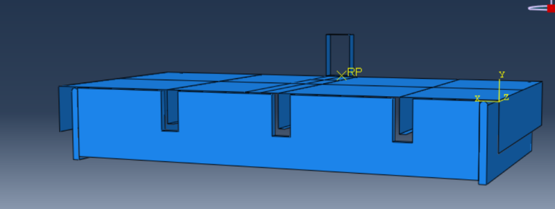
The model is pretty "basic": A 3d-deformable rig made of steel, with an aluminium plate that is simply supported on top of it. I run tests with both blunt and hemispherical indenters to find out how this affects the structural response. The impacts covered are in the low velocity regime, i.e. velocities between 0.4 - 0.6 m/s and inertia forces should not be a problem. Time period = 0.1 s
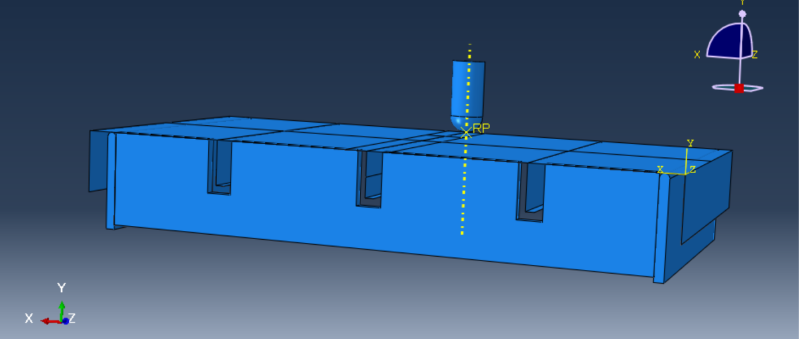
model_chyapv.png


model2_z0uw1n.png


The plate is modelled using S4R elements, while the rig is modelled with C3D8R elements. The nose is discrete rigid.
The General Contact-algorithm is used in the simulations, with some excluded pairs (surface-to-surface between rig/plate and indenter/plate).

The problem I am having (as you can see from the plot below), is that the model is to stiff. I also have a "bump" in curve in the first steps of the analysis. I have made sure that the initial gap between the nose and the plate is sufficient (greater than the shell thicknes) and I have also implemented the smooth step-amplitude. Material properties used in the model are identical to the ones used in the laboratory.
The mesh size and the friction coefficients does not really have that big of an impact on the results.
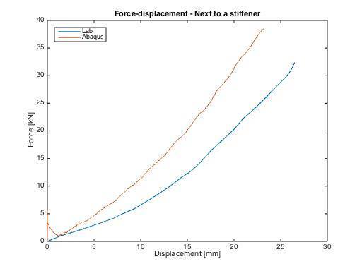
13022449_1097233163633522_949483020_n_o4ir8c.jpg


Do you guys have any tips or input on what can be wrong with my model?


Thanks,

Even (Norway)
 
Replies continue below

Recommended for you

Greetings Even,

I would check the following:

1. NLGEOM = ON
2. Mass scaling (maybe it is too high on auto)
3. Any damping can give you problems.
4. Mesh density (maybe mesh is too coarse)
5. Large strains can be good to use modified element types. Artificial stiffness might be needed for reduced integration and a fully integrated element might lock up. More about element selection here (it is a good source imo): Link


Here is a thread a while back which covered similar issues. Link

Good luck and please let us know how if you find the problem!

Oh, and if you have time and feel it is applicable, try implicit dynamics (since impact speed is low).
 
Appreciate the help, StefCon!

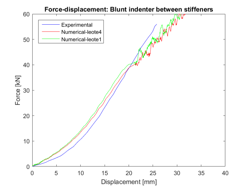
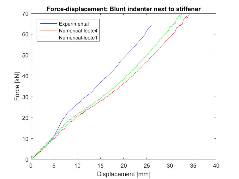
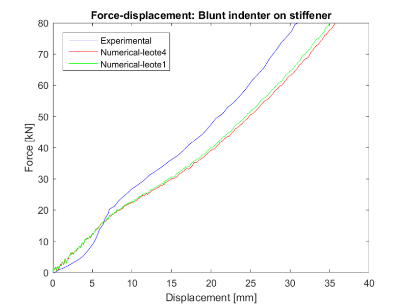
I expressed my self a bit unclear in the first post. The structure seem to be to stiff as long as the indenter hits the plate between the stiffeners, but too soft if the plate is hit on or close to the stiffener. (See the plots below. Leote4 = 20mm mesh and leote1 = 5mm mesh)

untitled_hmmbkj.png


next_too_stiff_t7emfd.png


on_stiff_amihjf.png


Running the simulations without the amplitude gave better estimations in the first part of the analysis (the amplitude seemed to introduce artifical forces before the nose hit the plate).
I have checked the mass scaling and I believe it works just fine on "auto". Damping should not be a problem either.

Since the model both under- and over-estimate the forces, I find it reasonable to believe that there can be something wrong with material properties. Do you agree?


Thanks again
- Even
 
Hello,
I agree to that, if there is plasticity. Otherwise I do not see the reason. Elastically should be fine.

Plot number 2 looks good up until 10 kN, right? What happens around 10 kN there? What kind of strains do you get? Is it maybe correct up until somewhere around yield stress? It should be cause the material data should be fairly accurate up until that point, imo.

I still think that (without having a complete picture of your model and mesh) that the reduced integration elements can give you some spooky results if there is high plasticity and/or bending in the elements (due to artificial forces). Checking the energies in history output could indicate where the problem is.

Tricky one!

/S
 
Plot number 2 (indenter next to stiffener): As you suggested, something happens at approx. 10kN. I have checked the model and there is at this point plastic strains start to arise in the stiffener which also confirms your "theory" that the model is correct up until yield stress. I will go through my material card and check for errors. Maybe I got my power law-parameters messed up.
A point (which I also failed to mention earlier) is that the experimental data I am comparing my results with are from a doctor thesis written in 2002 and no material parameters are provided for the stiffeners - which implies that I have used the same parameters for the plate and the stiffeners. Consequently, this is not that good of an estimate since the structures are made up from extruded aluminium profiles. Still, I don't think that explains all the difference alone.


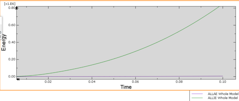
I don't have that much of experience with hourglass control, but I know that the artifical energy should be small compared to the internal energy. Below is a plot of ALLIE and ALLAE. Does this seem okay? Artifical energy stable at 1*e^3 and the interal energy has it max. value at 850*e^3. The link you provided suggested a threshold value of 1%, but for how much of the analysis is this "valid"?

Uten_navn_nx1dig.png
 
Hi,
Did the thesis reference to any material testing? If so you could maybe replicate the test in Abaqus and fiddle with parameters (parametric study) until you get a more accurate material data.
If you have time to dive into it, ASME VIII, division 2, some apppendix, has a way to make a material curve. I've found that one to "look better" than those power laws.

I haven't worked that much with explicit so I am not certain about the energies. I suggest plotting all of them in excel and just go through them and identify those that you know to begin with (like kinetic energy). My guess is that for slightly lower impact speeds, Implicit dynamics could be easier to use (replace step).

Another thing (since you are using explicit): Are you using double precision for the solver? How dense is your mesh (elements through thickness)?

Br,


Hi,

As it turns out, more accurate (plastic) material properties in the stiffener has a big impact on the final results and I think it is safe to say that this explain most of the difference we have seen between the numerical and experimental data.

(FYI: I am using double precision for the solver and the analysis is completed with 5 elements through the thickness. I couldn't find any aberration in the energy quantities, which (hopefully) indicates that the model is working they way I want it to!)


Thank you very much StefCon - I really appreciate the help!


-E
 
Thank you. My pleasure. It is fun to discuss these things.
 
Status
Not open for further replies.

Part and Inventory Search

Sponsor