Continue to Site

Eng-Tips is the largest engineering community on the Internet

Intelligent Work Forums for Engineering Professionals

  • Congratulations GregLocock on being selected by the Eng-Tips community for having the most helpful posts in the forums last week. Way to Go!

Impact of the SC current on transformer winding mechanical withstand capability 3

Status
Not open for further replies.

cuky2000

Electrical
Aug 18, 2001
2,133
Does the available short circuit (SC) on the primary side of a power transformer have any impact on the winding mechanical withstand capability?
For example, there is any difference in selecting a transformer wit fix impedance if the primary SC is 40 kA or 80 kA?
 
Replies continue below

Recommended for you

I'm speculating but I would have thought that since the current is effectively limited by the impedance, and the mechanical withstand rating would be most relevant for a through fault on the low side, that the extent of the withstand wouldn't be dependent on the high side fault level.
Or another way of putting it, if the mechanical withstand is on the basis of an infinite bus on the high side, then its irrelevant as to what the actual high side impedance is. A lower TX impedance would obviously require a higher mechanical withstand, or possibly high side protection to attempt to limit the internal stress imposed on the windings.

Of course, there are some experienced transformer manufacturers here, I'd also be interested in their opinions, as there are some different options in the construction of the transformer that may be relevant.

EDMS Australia
 
Yes, it is required to mention the SC level of the power system at the location of the transformer. This is as per IEC 60076-5.
The standard indicates typical values (Table-2) which are taken by the manufacturers if nothing is mentioned in the tender specifications.
Depending on how large is your system, the typical values given may be right or not.
Hence, it is in the interest of client, to mention the SC levels in the transformer procurement specifications.
 
See IEEE C57.12.00. If specifying a category III or IV, you must specify the system impedance ahead of the transformer or the manufacturer will use the tabulated values. Since this value might be subject to change, we specify an infinite bus system to cover all possibilities.
 
Stevenal,

Thanks for the info. We found out that the current Std IEEE C57.12.00.2015 test transformer with 80 kA on the 242 kV side. However, the same standard of the previous Std version of 2010 uses 126 kA in the HV side.

Does anyone know if this applies to 3 winding autotransformers tested with secondary and tertiary shorted?
 
We also checked the IEC 60076-5 and use a test default value for 242 kV for 20 kA for the European market and 25 kA for the US market if not specified by the buyer.
 
The fault level of primary system has effect on the fault current through transformer windings. Hence the mechanical forces (varies approximately as the square of the fault current). So when fault level increases from 40 kA to 63 kA, system impedance in series with transformer impedance reduces and hence fault current through winding goes up. This effect of system fault level is more with larger MVA transformers.
As example consider a 20 MVA & 500 MVA transformers connected to a primary with fault level 20,000 MVA. For 20 MVA transformer (Z=8 %) the system impedance will be 20x100/20000 =0.1% ie total impedance become 8.1 % (1.25 % increase) Consider a 500 MVA transformer (z= 15 %)System impedance will be 500x100/20,000 =2.5 % ie total impedance become 17.5 % ( 17 % increase in impedance)
 
prc, good observation regarding the impact of the source strength on the mechanical forces on the transformer.

I found interesting that the default value per latest IEEE Std for 230 kV transformer is 80 kA at X0/X1=1 and in the IEC Dtd 20kA.

Assuming if a system has SC of 80 kA at Xo/X1< 1.
Q1) Any thought about how to compare that with the standard test values?
Q2) What about specifying a source SC = Infinite?

 
As Stevenal mentioned above, I feel the best will be to speoify source as 'infinite' as a standard for all grid connected transformers.
I don't think this will add to cost, but will provide better flexibility.
 
Hi RRghunath,

I having trouble to understand how physically an infinite source is achievable at the test lab.
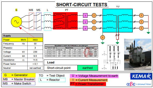
Below is a summary of typical SC test at one of the larger test lab in the world by Kema in the Netherland. Notice that the source, in this case, have a finite power capacity of 3933 MVA.
I wonder if certify test report with an infinite source is based on estimated calculation or actual infinite source test value. Any though?

.....
Transformer_-_Short_Circuit_Test_knlmci.jpg
 
Luckily, the short circuit test is neither a routine nor design test for class I or II power transformers per IEEE. It's calculated. And I suppose if we were to have an issue with our finite source we'd have some recourse.
 
cuky2000, Stevenal has answered the point you are making, I hope.
In case of HV/EHV grids, the source impedance is low. For the large / grid connected transformers, the SC test is not a type or routine test (to be proven only through calculation).
I agree with you for distribution transformers and in that case, a realistic source fault level shall be indicated in the tender specifications if the same can be higher than the typical values indicated in IEC.
 
1) I don't know why IEEE is indicating such a high system fault level. In US do you have 80 kA 230 kV breaker? When any fault level is specified, breakers also should be available. Any way I shall study and come back.

2)Cuky- As shown in my calculations, the effect of system short circuit level on transformer winding fault current becomes critical with large transformers; it can be seen in the calculations, when system fault level is considered, the winding current comes down by 17 %. In case of distribution transformers it may be 5% reduction, considering 500 MVA fault level.

3) During short circuit test at power labs, invariably we consider system fault level for calculating winding fault current to be applied. KEMA has special generators to apply total of about 10,000 MVA. But in effect we will not get it at transformer terminals due to large drops in connections, transformer impedance etc. Two years back my factory (from India) got short circuit tested at KEMA a 315 MVA single phase 765 kV GSU, the highest ever at KEMA. Earlier we had tested a 265 MVA 420 KV single phase GSU there.

4) True, short circuit test is a special test as per standards, but in India utilities are asking for this test on each design. With large transformers,short circuit test cost is nearly 60-80 % of transformer unit cost. In last 15 years my factory has short circuit tested nearly 10 large transformers at KEMA and 20 units in Indian labs. We ship the transformers to Netherland ports and from there take by barges through Rhine river to Arneihm, KEMA lab. Transformer is assembled on the barge and oil filled and processed before offering for test. Transformer is tested as on barge as there is no lifting capacity for such large transformers weighing over 250 tons. Now we have an on line short circuit test lab in India(Bina,Madhya Pradesh)for testing such large transformers.

5) Raghunath,system short circuit level is more important for large grid transformers and in case of DT impact is less. See my calculations.

6) In India we did short circuit test first time on a power transformer (till then only DT were tested) -Railway track side transformer-way back in 1984.Self volunteered (as other OEMS were not accepting the request of Indian Railways) to do this at Indian lab and fortunately it was successful on first attempt.
 
Prc,

In the US there aré pockets of very high fault currents. We are in progress installing multiples breakers rated for 90 kA and targeting a design for 80 kA due to debating per system X/R >17 witch is the upper limit of the breaker rating per the standard. Fill free to search for a dead-tank breaker PMI90.

One of the multiple unusual challengers beside the grounding, TRV issues, large electrodynamic forces in buses and already procured equipment purchase per current utility standard not specific developed for 80 kA.

Reviewing existing 3 winding, 100 MVA transformers units required to be connected to the substation designed for 80 kA with a system Xo/X1= 0.70 we initially were concerned that the default SC current PER IEEE Std C57.12.00-2015 is 80 kA at Xo/X1=1.0 that is equivaleb to less than the systen 80 kA @ Xo/X1=0.70.

Fortunately, the existing transformers were build earlier per the IEEE std C57.12.00-2010 that specify a SC current test of 126 kA for a 242 KV with Xo/X1 =1. The preliminary accessment indicates that the transformer can be used in the 80 kA system with sufficient margin after derating the source test current.

This was a close call. Otherwise, the project will be delayed and expend significant effort and resources procuren new units and tested at very high SC
 
Prc,
Stil I have some curiosity regarding the lab source capacity. The Kema generators of 10,000 MVA equate to ~25 kA at 245 kV.

If test current larger than 25 kA is required, how physically the SC test is performed to account let say 126 kA or an infinity source?

My guess is that the test lab will provide an estimate value based in calculation reducing the source impedance. For Example, Itest = V/(Ztransf - Zsystem) . For very large or infinity source, Zsystem~0.
 
cuky,KEMA has recently increased number of generators and current power available is 15,000 MVA. When a transformer of 100 MVA with 10 % impedance is short circuit tested at KEMA, there is need of only 1000 MVA at transformer terminals ie 10 times rated current at 220 kV side and not 80 kA. Effect of this 80 kA fault level is only for deciding the fault current through winding. When system fault level goes up, transformer fault current will only marginally go up as per calculations given earlier.But generator power has to be 4-8 times the transformer fault MVA due to the drop in internal impedance of generator and connections.

At power lab, rated voltage is applied to HV with LV shorted condition. The short circuit current through transformer is varied by adjusting the applied voltage but limiting to max 115% to avoid over fluxing of transformers.
 
It is worth to mention that the short circuit generators in KEMA are single-phase units, so that the short circuit power values are 1-phase and not 3-phase. Obviously, equivalent 1-phase connection scheme, is adopted.
On the contrary, when performing the short circuit withstand test in grid connected labs (e.g. CESI), the network impedance dictates the maximum available short circuit current. Both 3-phase and equivalent 1-phase test can be performed, with a pre-set short circuit on one winding, or energizing the transformer at no load and, when the inrush is over, performing the short circuit test by means of a circuit breaker on the LV side.
Given the high short circuit power at the test lab (generally, above 25 GVA), sometimes is necessary to adjust the short circuit current by connecting current limiting reactor in series with the circuit, in order to match test requirements.
This limits the maximum rated power of the tested unit. The larger units I've ever seen tested there are 400 MVA 400/230 and 400/155 kV autotransformers; in the next months a 600 MVA 400/230 kV unit should however be tested.


Si duri puer ingeni videtur,
preconem facias vel architectum.
 
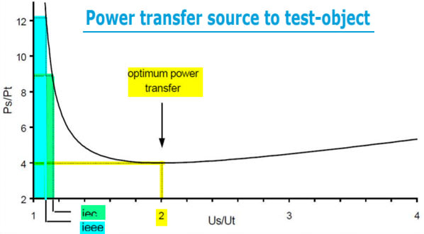
The normalized curve below was extracted from a KEMA publication and is associated with the SC test performed in transformer and other equipment. Please help us with the following:
1) How should the curve be interpreted to size the test source?
2) Indicates how an infinite source is represented in the curve?
3) Does the SC test reduce the transformer life expectancy?


Thanks

Power_Transfer_Source_to_test-object_Transformer_umeqfc.jpg
 
1)KEMA generators are 3 phase units and if capacity permits short circuit test is done in 3 phase mode. But when the capacity limitations arise (generator capacity must be 6-10 times the transformer fault MVA) single phase or 1.5 phase mode is adopted. In pre-set SC test (KEMA) inrush current will not occur as the excited winding(HV)will be outermost with inner winding shorted

2) This curve connects -Ps -source(generator capacity) Pt -Transformer short circuit MVA Us- Voltage at source end Ut -Voltage at transformer terminals. Standards generally limit US/UT to 1.15 to avoid over excitation. With Infinite source Us/Ut =1 No reduction in life expectancy due to SC test.
 
Status
Not open for further replies.

Part and Inventory Search

Sponsor