Eng-Tips is the largest engineering community on the Internet

Intelligent Work Forums for Engineering Professionals

  • Congratulations waross on being selected by the Tek-Tips community for having the most helpful posts in the forums last week. Way to Go!

Impedance value on water-air free surface

Status
Not open for further replies.

pilafa

Mechanical
Jan 29, 2007
14
0
0
ES
Hi,

I have an open tank filled with water, with an ultrasound source in it. I calculate the pressure in the water with FEA.

I would like to study only the water, and avoid meshing surrounding air (which I think is not necessary anyway). For that, I impose an impedance value on the free surface (water-air interface).

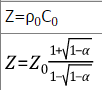
Is that a good approximation to simply use Z = rho*c = 1.2 kg/m^3 * 343 m/s ?

Thanks
 
Replies continue below

Recommended for you

No, you have to treat the boundary as (mostly) reflective, with energy reflected back into the water being R, and R = (Zw - Zair)^2/(Zw + Zair)^2. Using Z=rho*c means the energy is perfectly transmitted at the boundary. In reality, the surface can have some admittance, with energy being transmitted to the air, or dissipating as surface waves.
 
Thanks for your answer btrueblood.

In my FEA, I need to input some Z value. So, I found this formula (I guess it is equivalent to yours):

3_c6v8kn.png

(Source)

In this formula, alpha is the "absorption coefficient" (I assume that: alpha+R=1)

So, when:
alpha = 1 -> Z=rho_0*C0 -> the energy is perfectly transmitted at the boundary (like you said)
alpha tends to 0 -> Z tends to infinity -> the energy is perfectly reflected at the boundary -> Rigid Wall!

For a real surface, alpha is in the range ]0,1[

Now, the 1 million$ question: which value of alpha should I use? I suppose there is no clear answer to that. It depends on many factors.
You suggest that it is mainly reflective (alpha close to 0). But if the vibration intensity is so important that I can see water moving and bubbling, I guess the value of alpha will be higher.

---

Same question with the walls of my tank: is there an "easy" way to find alpha in function of material constant (c, rho) and wall thickness?

Thanks
 
Hi,

In order to assess my doubt, I built three simple models:

M1:
- Tank of water with oscillating pressure in the bottom
- Surrounding air outside the tank (on the top) with far-field condition on the air domain

M2:
- Only the tank, with a rigid-wall boundary condition on the water-air interface.

The rigid wall is perfectly reflective, so that corresponds to btrueblood's suggestion

M3:
- Only the tank, with Impedance boundary condition (Z = rho*c = 1.2 kg/m^3 * 343 m/s) on the water-air interface

That corresponds to my initial guess

What I observe is that M1 (water and air mesh) gives the same answer as M3 (Z=rho.c).
I am surprised, because I have reasons to believe that btrueblood is right and that the wave should be reflected on the water-air interface (like in M2).

Any explication?

Thanks
 
What is the "far field condition" you impose in model #1? Are you modelling an air volume above the tank?

Can you do a time-domain solution and look at the waveforms at the boundary? The phase of the reflection from the air-water boundary (no surface normal pressure, reflected wave cancels incident wave at the boundary) should be 180 degrees from the phase of the rigid wall reflection.
 

- My FEA program has an option to automatically define a "far field".
- Yes, I am modelling an air volume above the tank
- I will try the time-domain test when I have a chance

- Any comment on the previous post (how to choose alpha values)?

Thanks
 
The the fraction of incident power reflected by the free surface is

R=[(Zwater-Zair)/(Zwater+Zair)]^2

with a water boundary and far field condition, no reflection


Status
Not open for further replies.
Back
Top