Continue to Site

Eng-Tips is the largest engineering community on the Internet

Intelligent Work Forums for Engineering Professionals

  • Congratulations SSS148 on being selected by the Eng-Tips community for having the most helpful posts in the forums last week. Way to Go!

imposing a displacement profile on a structure

Status
Not open for further replies.

ggcdn

Structural
Dec 14, 2013
142
I have a displacement profile (displacements at every story) that I would like to impose on a gravity frame model. Does anyone know whether this can be done in ETABS?

I see there is an option for joint loads > ground displacements. But that seems a little weird to add a restraint and then assign a displacement to it. I also see there is generalized displacements and these can be monitored with displacement control... but I can't figure out how to piece this all together.

Is this even possible with ETABS?
 
Replies continue below

Recommended for you

SOA said:
But that seems a little weird to add a restraint and then assign a displacement to it.

This is the way to do it from memory. I agree the name is somewhat confusing given your intended use.
 
Rahul, in this case I do not know the load pattern, I know the displaced shape and I want to determine the demands in the gravity frame. So its not a traditional 'pushover'
 
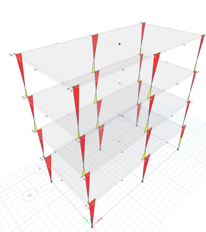
Update: I made a simple model and put a node at the center of the diaphragm. I gave the node an x-direction restraint and a U1 ground displacement of 20in. I then switched the load case to nonlinear static using the default settings. This seems to be working.

Test_Frame-v17_cwcgbj.jpg
 
Sonofatkins said:
I made a simple model and put a node at the center of the diaphragm.

With diaphragms, a node automatically appears at it's centre, and one can't himself put the node there to the diaphragm ...

Sonofatkins said:
I gave the node an x-direction restraint and a U1 ground displacement of 20in.

That node is usually no selectable, and so one can't (i suppose) assign a restraint to it.

How did you manage to do it !!??
 
Rahul, I drew a user joint (node) at approximately the center of diaphragm, and then assigned it to the diaphragm. I didn't use the auto-generated joint.
 
Got it... you inserted a node in a beam that was passing through the diaphragm centre, inserted at that location (as seen in the pic)... it then automatically got added to the diaphragm. On this node, you applied a support... and then assigned a support displacement as a load... [thumbsup2]
 
Pretty much, except there are no beams in that model. The lines are gridlines
 
I'd point out if using a semirigid diaphragm this method won't work to well, it's analogous to putting a large point load on the diaphragm and it will just deform locally and you'll get structure closer to the point of application deflecting further than those further away.

In the case of a semirigid diaphragm you might consider applying the deformation at multiple points on the floor plate along beam lines to get the entire floor plate mobilised to a similar deflection. Though in doing this you are restraining the natural z axis twisting that might want to occur depending on how irregular your structural system is. Temporarily switching to a rigid diaphragm might also be an option depending on what you are ultimately trying to achieve.
 
Yes Agent666, that is correct - semi-rigid diaphragms would make this procedure inaccurate. I suppose you would need to input the displacement at every vertical element independently to get somewhat correct frame forces, but that sounds like a terrible experience.
 
Status
Not open for further replies.

Part and Inventory Search

Sponsor