Continue to Site

Eng-Tips is the largest engineering community on the Internet

Intelligent Work Forums for Engineering Professionals

  • Congratulations IDS on being selected by the Eng-Tips community for having the most helpful posts in the forums last week. Way to Go!

Improper service for existing pumps?

Status
Not open for further replies.

jari001

Chemical
Aug 9, 2013
478
Hi everyone,

I have a sump pit (see attachment for details) that drains via a lead lag pumping system. The fluid being pumped out is 90oC WFI (water for injection/very pure water). I am taking the vapor pressure of the water at this temperature to be 526 mmHg. The pit is arranged such that the pumps are bolted to the top of the sump pit, have legs that extend into the pit and have 2" clearance from the floor of the pit. The maximum distance from the surface of the water in the pit to the center line of the pump is ~70 inches (70 inches length of the legs is by best approximate to center line of the pump given the drawings).

Pump details:
GPM = 25
Head (ft) = 110
RPM = 3500
Discharge line is 2"
HP = 3

One of the maintenance techs has noticed that this pit is pumping out slower than normal. My initial diagnosis is that the pumps were
not designed for this fluid temperature, so the NPSHr is too high (Can I get a stupid check on this thought?). The first complicating factor is that the stream of water into the sump generates a lot of steam as it flows into the and waits to be pumped out. Could the steam alone be forming a vapor lock situation that impedes the flow?

If further system details are needed, please ask and bear with me as I hunt for them. I will be on site tomorrow so I will have a better chance to get information.

Thanks,
~J
 
Replies continue below

Recommended for you

I don't see an attachment, but here's a few things to think about anyway.
Were the pumps previously operating satisfactorily under the conditions stated? If so then there is likely another cause apart from fluid properties for drop in performance. Clean fluid, but can anything drop into the pit causing blockage? Have any changes been made to the discharge piping arrangement? Wear in the pumps?
What is the NPSHr? Can you provide the pump performance curve? Are the head/flow numbers from the pump nameplate, or actual data. If actual, how does that compare with the design point from the pump curve?

Sorry, so many questions, but not sure how else I can help.
 
Slower than normal which indicates it has been working OK previously.
Has temp changed?

It is a capital mistake to theorise before one has data. Insensibly one begins to twist facts to suit theories, instead of theories to suit facts. (Sherlock Holmes - A Scandal in Bohemia.)
 
With a suction lift condition NPSHa = barometric pressure (ft) - static head on suction lift (ft) - friction losses in suction piping (ft) - vapour pressure of liquid (ft)

[ol 1]
[li]90 oC = 194 oF[/li]
[li]absolute vapor pressure of water = 24.3 ft[/li]
[li]S.G water = 0.965, therfore the barometric pressure available (ft) = barometric pressure (ft)/.965[/li]
[li]Suction lift = 70" (5.8 ft)[/li]
[li]you fill in the rest[/li]
[li]I can tell you right now you do not have enough NPSHa[/li]
[li]Get the NPSHr from the manufacturer[/li]
[/ol]
It is possible you also have air locks in the piping. You do afterall have a lot of vapor being offgassed. Check your pump and piping arrangement for trapped high spots.

 
Sure, available NPSH can be calculated, but pump design data is needed to check whether NPSHr is achieved. It is inferred from the original post that the pump performance has deteriorated recently ("this pit is pumping out slower than normal"), so any investigation needs to focus on what might have changed, in my opinion.
 
The poster asked for our thoughts on whether the NPSHr was too high. I gave him how to calculate NPSHa. It is up to him to find out from the pump manufacturer what the NPSHr is. BTW his assumption that the vapour pressure is 526 mmHg (23.5 ft) is incorrect. At 90 oC (194 oF) the vapour pressure is actually 24.3 ft. Therefore it is important to get the base numbers correct if he wants to get an engineered answer that he has confidence in

The poster did not say if this was a long time installation or a new installation or a change in service conditions. All he said was that he thought the pump was not designed for this temperature.


The OP has clearly indicated that pumps are mounted above the sump- nothing about submersible pumps.

It is a capital mistake to theorise before one has data. Insensibly one begins to twist facts to suit theories, instead of theories to suit facts. (Sherlock Holmes - A Scandal in Bohemia.)
 
You are right! I will correct my posts :). In my world when a "sump" is talked about we associate it with a sump pump. Next time I will read more closely. There are sump pumps made for this operating condition. How well they work needs research
 
👍

It is a capital mistake to theorise before one has data. Insensibly one begins to twist facts to suit theories, instead of theories to suit facts. (Sherlock Holmes - A Scandal in Bohemia.)
 
At atm, with water sg=0.965, head of water = 10.7m
Assuming @QualityTime value of sat vap pressure of water at 90degC = 24.3ft = 7.4m
Assume for now that head loss in suction line = 1m of water head
Suction lift = 70inches = 1.8m

So NPSHa = 10.7-7.4-1-1.8=0.5m (!)

A typical centrifugal pump NPSHr= 2-3m or so , and if you add a metre head margin, we are short on NPSHa by about 3.5m or so.

Is there a foot valve on the suction leg entrance in the pit? How do you prime this pump's suction line for startup ? Any devices on this suction line close to pump suction nozzle elevation that could be pulling in air for example?

By these calcs, and if this suction line is airtight, preliminary assessment would be that water vapor pressure should be no more than 7.4-3.5 = 4m, which translates to 39kpa abs vapor pressure, which corresponds to water temp of 75degC max permissible. Why is this water so hot here?
 
From the data given and the description, it would appear that the pumps are likely to be cavitiating on a regular basis. How regular isn't stated, i.e. how many times a day do they operate and for how long?
How old are these units?
What's the low level shut off set at in terms of distance from CL of pump?

Best guess / thing to look for is that the impellor has become eroded and has lost capacity.

That ignores the obvious issues of pipe blockage / scaling, debris etc

Is the water now hotter than it was before?

Remember - More details = better answers
Also: If you get a response it's polite to respond to it.
 
My take on it is that if the pump is above the pit, and the water is almost boiling, you're doomed from the beginning.

 
Whatever the actual process conditions, it has been noted that "this pit is pumping out slower than normal", which suggests that the pumps have previously operated satisfactorily. (Sounding like a cracked record here.)
 
I would just concentrate on the data on hand and leave the history to the people who are actually involved in the issue to sort out. Numbers are black and white. History on the other hand is he said...she said. The poster got a solid engineered answer/confirmation for free. The participants on this site have a genuine interest in the subject and have a genuine interest in helping people.


An explanation may be that a brand new cavitating pump still pumps water but not as much as it should. A "older" cavitating pump will start to put out less and less over time as the impeller gets destroyed
 
Fair enough, it will be interesting to find out what the OP finds.
 
Attachment is included now, sorry about that.

This sump pit is at least 8 years old and I believe it has seen minimal usage in that time if you compare running hours to total hours since install. I am trying to see if the PLC has logged total running hours for the pumps. The lead pump will turn on at 24in and turn off at 12in. The lag pump will turn on at 36in and off at 24in. The P&ID says these pumps are self priming, but I don't know how the priming mechanism works, meaning I don't know if the pump has some way to ensure there is liquid left in the pump body after it stops turning. Poor ownership of this equipment is making documentation hunting very fun.

@Qualitytime I will check if my source on the vapour pressure was off.

@georgeverghese The water waste is part of a clean in place cycle (CIP) for a skid that produces an injectable product. The hot WFI supply to the processing suite is 90oC.

@LittleInch and Artisi I've been told by utilities that the average temperature of the WFI has been constant during the lifespan of this sump pit.

@JohnGP - I will look into those questions; this sump pit and associated equipment has sort of sat around without anyone really fussing with it, leading to poor documentation retention. It's getting some attention now because it is potentially being impacted by the restart of the skid that is supplying the waste to the sump.
 
 http://files.engineering.com/getfile.aspx?folder=dee02ee9-06e8-4c70-8367-d0750705c71c&file=Sump_pit_pump_picture.docx
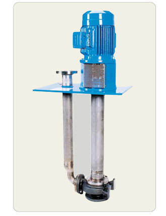
This looks to be a typical vertical sump pump:


This type of pump will be a good choice for this application.

Do you have a flow meter on the pump to verify the discharge flow? If not, see if you can install an ultrasonic strap on flow meter. Has the sump ever been cleaned?

Have you compared the original design requirements of this pumping system to the new requirements?
 
jari001

There is a big difference between your photo and your drawing / schematic

Picture shows what looks like a vertical sump pump with above ground motor. Simple, effective and should avoid any NPSH issues and inherently "self priming" as the pump is below water level when turned on.

Like this:

verticalsumppumps1_tadzfy.jpg


Drawing though shows a surface mounted pump with 2" "suction pipes"

You need to first work out which one is correct.

You didn't say there were two - it could simply be that one of the non return valves is passing. Have they tried it by isolating manually one or other of the pumps?

Given that for the low level ( lower than 24") both pumps operate in parallel, it could be one has become less effective than the other and hence takes more flow, but would also mean that when only one pump is running it is probably sitting on the non return valve to allow automatic start / stop

So currently the NRV on the pump discharge is looking like a good candidate....

As bimr says, a portable flow meter is very useful to see what is going on.

Remember - More details = better answers
Also: If you get a response it's polite to respond to it.
 
bimr and LittleInch have nailed it with the pump type - certainly appear to be vertical sump pumps. As suggested you need to perform a flow test on each, but you also need to identify the pump model to check results against its performance curve. Isolate each in turn, then with isolation valves open to check non return valves performance.
Flow rate might be able to be estimated by recording level transducer output over time of pumping, if you don't have a flowmeter installed, or access to a portable one. (I have measured level change on hands and knees with a tape measure, but the sketch seems to indicate that this pit is sealed).
 
For the lead pump, at a mean level of 18inches minus say 6inches from the bottom of the pit to get to feed nozzle, we have a static head of just 12inches of hot water at 90degC, which turns out to be 3kpa, making total pressure to be 104.3kpa abs at the feed nozzle. Sat vap pressure of hot water at 90degC = 7.4m = 71kpa abs, which leaves 104.3-71 = 33.3kpa as net suction press, which = 3.5m of NPSHa which would be typically adequate.
So there is some other problem : blocked suction or discharge check valve leaking on parallel pump ??
 
Status
Not open for further replies.

Part and Inventory Search

Sponsor