Yes, you are correct.
The impulse generator is used to test the transformer insulation withstand regarding voltage transients.
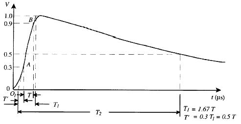
In very simple terms, the generator charges a series of capacitors and then discharges them over the test subject when the charge level is right. Some resistors are fitted in the circuit to control the shape of the wave, as the generator needs to be adjusted to match the standardized impulse waves defined by the relevant standards, like this one:
With T1 = 1.2 μs and T2 = 50 μs for lighting impulse wave, for instance.
Mainly there are two types of test you can do:
Lightning impulse (to simulate an overvoltage caused by a lightning strike) and
Switching impulse (this simulates the voltage transient caused by a breaker trip).
The lightning wave can also be "chopped" by an external air-gap to simulate more severe transients and the test are then called simply
chopped wave if the wave is chopped after the crest value is reached or
front-of-wave if the chopping is done before the crest, on the "ascending" part of the wave.
According to the power and voltage of the transformer you get different tests to perform. For ANSI world:
- IEEE C57.12.00 on table 17 states the tests to be performed (routine, design and others) for each type of transformer (distribution, class I and class II power transformers).
- IEEE C57.90 gives the test methods and the required sequence between them.
- IEEE C57.98 gives guide information on impulse testing techniques, interpretation of oscillograms, and failure detection criteria.
I tried to keep it simple, but is a broad and complex subject.
Hope it helps.