Continue to Site

Eng-Tips is the largest engineering community on the Internet

Intelligent Work Forums for Engineering Professionals

  • Congratulations Danlap on being selected by the Eng-Tips community for having the most helpful posts in the forums last week. Way to Go!

Inclined datum and degrees of freedom

sendithard

Industrial
Aug 26, 2021
186
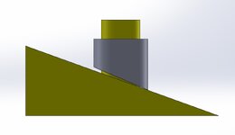
In this mock example I have a yellow fixture with a cylindrical boss as Datum A, then an inclined Datum B at 20 deg Basic. We slip the gray part over Datum A which let's just say expands b/c it is at RFS, so Datum A is locked in solid.
'
I don't think I've seen an example in the standard for an inclined datum B with Datum A as cylindrical.

I simulated the part machined 2 deg wrong just for visual. My intuition says the inclined datum arrests the rotation but I have a software saying rotation is still in play. I disagree.
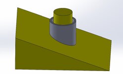
YELLOW_GAGE.jpg
SIDE VIEW.jpg
 
Replies continue below

Recommended for you

The primary RMB cylindrical datum feature will lock down four degrees of freedom, leaving only axial movement and rotation around the cylinder's axis. The slope that provides the secondary datum will eliminate movement along the axis and rotation around it.

If the software doesn’t agree, it's talking nonsense. Which software is causing trouble?
 
It's a weak constraint. Turning the part causes the part to move axially. It is trying to stop 2 degrees of freedom with as little as one point of contact.

If the plane was parallel to the axis of the cylindrical datum feature it could fully arrest rotation with no effect on translation; if it was purely perpendicular it could full arrest translation with no effect on rotation.

Usually I have seen this used with 45º slopes to lock rotation, but it often doesn't solidify axial motion until the sloped parts are forced out of alignment to wedge against the central rod or within a cylinder as is often used in bicycle handlebar stems being force fit to steering tubes.
 
I agree with 3DDave on this one.
"eliminate movement along the axis and rotation around it" as I put it earlier was not quite right.
 
With that said,
I think that considering datum simulation rules, the secondary sloped datum feature would be treated as an unstable one, and one would need to find the optimal condition that minimizes the gap between the datum feature and the datum feature simulator by the constrained least squares method. This should effectively constrain those last two degrees of freedom anyway for conformance evaluation purposes.
 
Appreciate your replies. What 3DDave made sense b/c when I modeled the assembly in Solidworks the inclinded datum removed all the dof, but in GOM inspect it does not. I have an immense respect for the GOM software so I was intrigued when it didn't arrest the rotation. Solidworks is assuming a perfect mating inclined surface which would, but in reality Dave hit the mark that it become a point of contact. We had an intense debate at work about this, and I was against it, then they worked me into thinking it did, and now I understand it is a little gray area somewhat, ideally you want to let something else control the rotation and in our case we have a much better surface.

Thanks.
 
Burnunduk,

The inclinded datum would be at a basic to the primary cylindrical axis so it would be simulated not from the datum feature(real surfcace) but from a perfect basic angle simulation. My interpretation is that it isn't one of those cases where you have the unrelated vs related mating envelope, but you simply create the setup as best you can to the basic degrees away from the primary axis and then when you drop the part down wherever it hits the sine plate is your Z plane perpendicular to the primary axis. Agree?
 
sendithard,
Regarding

" but you simply create the setup as best you can to the basic degrees away from the primary axis and then when you drop the part down wherever it hits the sine plate is your Z plane perpendicular to the primary axis ",

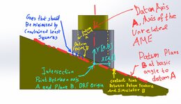
I agree with the begining of the sentence but I'm afraid I don't agree with the second half starting from "wherever it hits...". See the embedded image below. The DRF originates at the intersection between the two theoretical datums.

1000018550.jpg

(Note that I prefer to call the plane at an angle simulated by datum feature simulator B "datum B", and the intersection of the A axis with it is where the DRF originates. If I followed the inclined datum features figure from Y14.5 I would have to call the XZ plane of the DRF "datum plane B" but in my opinion it would be a mess).

Also worth noting, that the optimization for minimizing the gap is performed by rotating the part around the datum A axis.
 
Last edited:
Yea I agree with you, your origin is more proper than what I was imagining, I started confusing planar setups for inclined datums vs a primary as a cylinder which is not in the standard. I do need to share a weird thing with you once I get back to work tomorrow regarding this which may be interesting.

The constrained least squares you mention, I'd still like to discuss with you now. I'm not fluent in this, but I was under the impression is was more of a primary datum idea. The most simple idea was a Datum A plane that was convex and could rock. The constrained lsq would find the highs(somehow...perharps with gravity or centroid based on points measured) then adjust for stabilizing the rocker effect. Somehow if Datum A was a Cyl, it would find the highs, then adjust for instability to least square average out the rocking inside the cylinder....but at that point the rest of your datums are a slave in orientation to the primary so in our example of the secondary Datum B being an inclinded Datum isn't it absolute, being there is not adjustment to be had...it is what it is?

My thought was that the primary is an UAME and can be adjusted for constained lsq, but aftet that all datums are related and cannot be constrained lsq.
 
Last edited:
sendithard,
The end of my post "Also worth noting, that the optimization for minimizing the gap is performed by rotating the part around the datum A axis" Is also related to the constrained least squares method. Sure, the secondary datum plane is set to be at the basic angle to the primary datum axis. The "constraint" in this case is not only tangency to the high points as in the rocking planar primary case, but also the basic angle to the primary axis.
But as I mentioned, the part is rotated around datum axis A to the optimal condition for minimizing the gap per constrained lsq.
 

Part and Inventory Search

Sponsor