nivoo_boss
Structural
- Jul 15, 2021
- 130
Hey everyone!
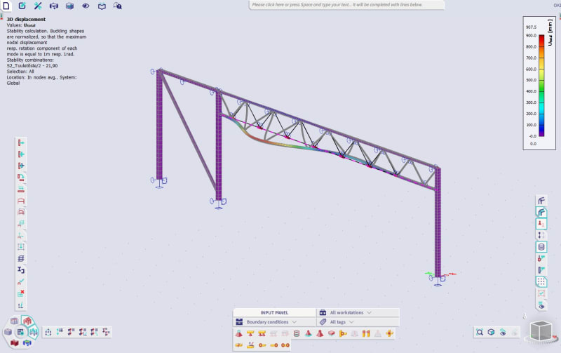
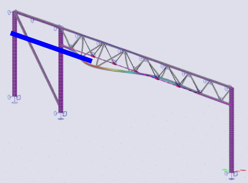
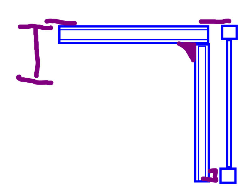
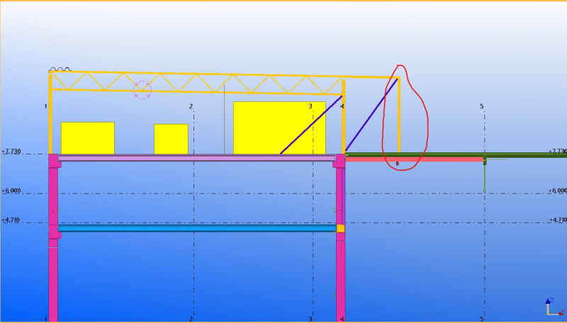
So I have this frame where I cannot have any brace members and also cannot have rigid column supports. So I'm thinking about making the frame's top joint rigid by connecting the truss's both chords with the columns and this way I can get a sway frame. The columns are SHS square sections and the truss on the pic is also made from SHS steel sections. I do not want to use an I-beam since it would be over 2x heavier at this span (~13 m) than a truss.
It's a small room (~6 x 12 m) for HVAC units etc and it's also quite low (around 4 m).
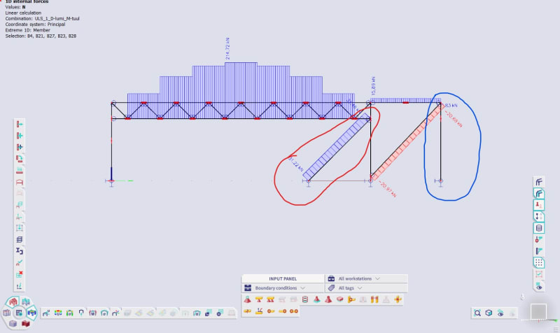
Ignore the right side of the frame - the right most column actually has a vertically sliding support and the diagonal is for supporting the top beam - the right side is basically a hanging structure over an existing roof for housing pipes etc.
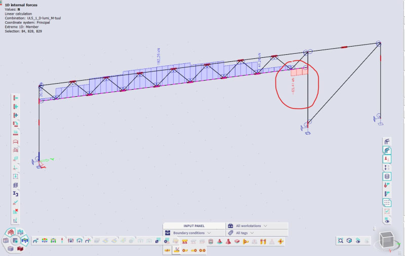
To my question finally. As you can see from the pic a compressive force of around 65 kN develops in the bottom chord of the truss at the last section.
Now the buckling length of the bottom chord is the same as the span (~13 m). And taking a compressive force of 65 kN at that buckling length takes a pretty large section. So my question is this - could I make the section just bigger at that last stretch of the chord by welding a thick steel plate under the SHS section for example and then would use that section's second moment of area to calculate it's buckling capacity at a buckling length of around 13 m?


