Eng-Tips is the largest engineering community on the Internet

Intelligent Work Forums for Engineering Professionals

Increasing the No load voltage of Transformer 5

Status
Not open for further replies.

NickParker

Electrical
Sep 1, 2017
396
0
16
NL
Let us consider a 11/720V, 5000kVA transformer with a percent impedance of 8%. This means that when this transformer is not loaded and when the primary is applied with 11kV, the secondary terminal voltage will be 720V.

And when this transformer is loaded to its rated capacity of 5000kVA, 8% of its open circuit voltage of 720, that is 720 x 0.08 = 57.6V will be dropped within the secondary windings of this transformer and only 720-57.6 = 662.4V will be availabe at it secondary terminals.

Am I correct? the nominal system voltage is 690V, now im thinking of increasing the no load voltage to 750V.
 
Replies continue below

Recommended for you

No, what you need for that is called regulation. The impedance of the transformer is highly inductive while, generally, load current is highly resistive. The resistive component of the load current (large) creates a voltage drop across the resistive component of the impedance (small) and the inductive component of the load current (small) creates a voltage drop across the inductive component of the impedance (large). The vector sum of those voltage drops will be much smaller than the impedance value.

I’ll see your silver lining and raise you two black clouds. - Protection Operations
 
1) Your name plate impedance is 8%. That means your 662.4V calculation is correct if you are loading the transformer to 5000kVA with a 100% inductive load only.
That is why we keep the LV winding closer to the core so that the mutual inductance is maximum thereby leakage impedance is lowered. If we keep the
HV winding closer to the core, then more leakage and low mutual resulting a severe voltage drop even at light loads.
That means if you load it with a 80% power factor load the output voltage will depend on the X/R ratio of the transformer.

2) I noted that your transformer primary is 11kV meaning are you in the IEC world?
If yes, then in the IEC world we normally specify the transformer (IEC60076) low side voltage at least 5% higher than the nominal system voltage (11kV-415V for 400V nominal)
so that the voltage drop is internally compensated. That means your transformer ratio is correct (11kV-720V) for me.
But if we specify an ANSI/ IEEE C57.12 transformer you will notice that the low side voltage is always equal to the ANSI nominal system voltages (138-13.8kV for 13.8kV nominal).
Hence any voltage drops have to compensated by either increasing the primary input voltage (or by tap adjustments).
Accordingly, the kVA rating is defined differently in IEC & IEEE.
 
Your required secondary voltage depends on the equipment voltage requirements and the voltage drop in the circuits leading up to the equipment. In NA, the standard nominal voltage is higher than the standard utilization voltage. For instance, nominal voltage of 480 V and standard motor voltage of 440 V.
 
Im am sure that that was a finger fumble, jgrist. I am prone to finger fumbles.
Respectfully, in aspirit of accuracy, in North America, 440 V was a standard system voltage in the 50's
Standard motor voltages are multiples of 115 volts,ie: 115V, 230V, 460V, 575V(Canada).

--------------------
Ohm's law
Not just a good idea;
It's the LAW!
 
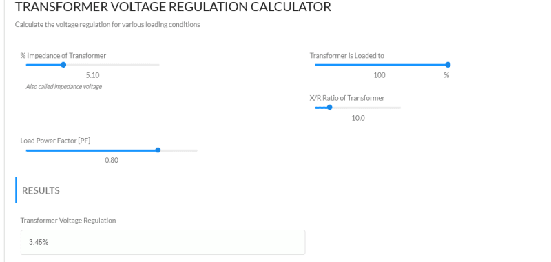
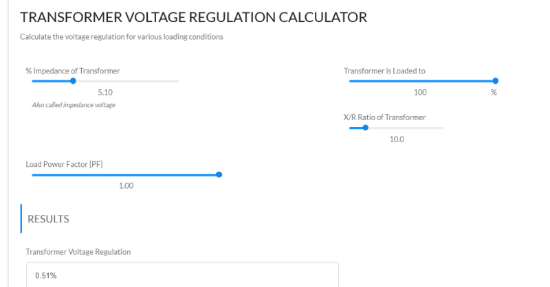
Here is an interactive voltage regulation chart.
Screenshot_2023-08-31_at_09-19-11_Voltage_Regulation_Voltage_Disturbance_ccfjan.png

Screenshot_2023-08-31_at_09-26-42_Voltage_Regulation_Voltage_Disturbance_kdhe7b.png

Notice the dramatic change in voltage regulation when the PF is improved from 0.8 to unity.
On the original, you may drag the blue dots to adjust the parameters.
You may change the;
% imp.
% loading
X/R ratio
Load Power Factor.
Interactive chart, scroll down
This is the best that I have seen.

--------------------
Ohm's law
Not just a good idea;
It's the LAW!
 
1) In the IEC world, transformer rating is the input kVA and in the IEEE world it is the output kVA

2) Regulation (voltage drop in % at any power factor of full loading) = IR cos theta + IX sin theta where IR= full load copper loss in kW/ rating in KVA (in %) IZ = square root of (square of percentage impedance-square of percentage IR) Cos theta= power factor of load.

 
 https://files.engineering.com/getfile.aspx?folder=b8106692-d335-4736-b1f4-26775f7dcff0&file=Volatge_Regulation_with_load_and_load_power_factor.docx
I don't know.
Hopefully someone will do a couple of spot checks to verify.
Interestingly, the site mentions that the regulation may be negative with a leading power factor.
I haven't seen that for decades, maybe for generations.
Back when PF correction was an art rather than a science, the challenge was to correct as cheaply as possible without driving the voltage too high at night and on weekends.
The cheapest PF correction was bulk correction, switched with a fused manual disconnect and left energized 24/7.
We would look at power bills for the preceding year or two.
We would look at the monthly KVARHrs and divide down to KVARHrs per hour.
We could then connect that many KVAR of capacitors and get rid of the penalties.
Unfortunately that would often take out the lighting as well due to over voltage.
The art came from creatively adding enough KVARHrs to get rid of the penalties without getting rid of the lighting.
We would often over correct the largest motors. That is, if it took 5 KVAR to correct the motor we would use 10 KVAR and let that correct a number of smaller motors.
The justification was that when the plant was running there would be small motors running when the large motor was running.
We would connect the capacitors to the motor terminals and save on contactors.
The running current of the over corrected motors was close to the uncorrected current so we did not often change the protection settings.
We had a lot of tricks, but many of them have faded from memory.
One habit was to drag a hand lightly over the capacitor banks when entering the electrical room.
A cool capacitor was a sign that an internal fuse had failed.
Yes, voltage regulation may be negative.
Another real world case on negative regulation.
A transmission line capacity may be limited by the ability of the OLTCs to correct line voltage drop.
I remember an instance where the capacity of an overloaded transmission line was significantly increased by the use of synchronous condensors at the load end.


--------------------
Ohm's law
Not just a good idea;
It's the LAW!
 
We in the utility generator world see both positive and negative regulation in action when we perform NERC testing on our generators. One of the requirements is to max the machine vars leading and lagging at both min and max loads and record the data. No problem swinging the gen bus voltage plus and minus 5% while connected to the grid. It’s kinda interesting when at the end of a longer line and you end up pushing the 115kV bus around few % in the process too and then get a call from the transmission dispatcher.
 
Status
Not open for further replies.
Back
Top