Reference Thread: thread800-419247
The referenced thread is fairly new and I have been working on an off-road IRS design that might bring some light to moving the Lotus lateral links.
It really helps to have a fresh paper design as you usually see more in the development of the geometry. To make a long story short, I was having problems making the lateral links do to the wheel camber what I wanted ...without putting the inboard links into the center section. My main problem was at the hub where the hub CV center was 5" outside and where I could mount the closest link mount points.
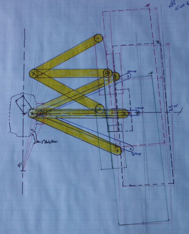
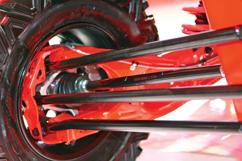
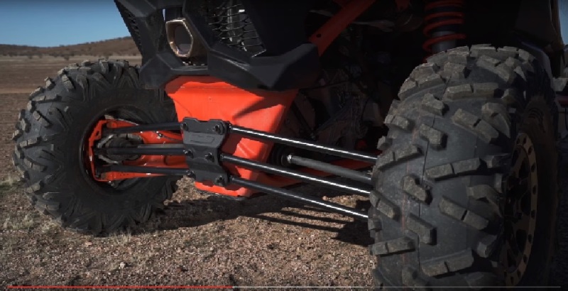
Offroad racers will understand this better, but here goes. I wanted 22" of wheel travel, with the bottom of the tire running along the same driving line through out travel. I also wanted the camber to not go positive up to 5* of body roll to the ground. I also wanted to minimize CV axle/half shaft plunge (desert guys are used to 4"), and maximize ground clearance while still preserving a tub in the rear for an ice chest, etc. I am an old draftsman and not a CAD guy and had to play a lot with different suspension systems and was getting no where until I read about "virtual points." This was the key to moving me forward. Some recent OEM and racer offroad suspensions with trailing arms and lateral links started to make sense. Long trailing arms have less plunge and more consistent "drive". I set that at 56" which mounts under the seats. Then I worked on the lateral camber geometry from the rear view...inline vertically, with the rear half shaft/hub/CV.
By placing the bottom link at the height of the half shaft (ground clearance), plunge went to almost zero. After working the camber curves and trailing arm radius, The bottom link was almost to the center of the car/differential and plunge was near 1/2". The top link, which is 12" above the bottom link/half shaft was just missing the IRS quickchange diff.
So those were my perfect "virtual points." Since everything rotates from the front trailing arm mount, I figured the inboard link mounts would be on a line from the "virtual points" to the arm mount. This allowed me to move the inboard link mounts forward toward the pinion and preserve the geometry. Right now, the geometry works great in moch-up and workiing toward figuring out the toe out problem. Usually that is "compromised/solved" by moving the arm mount inboard under the seats. Since the lateral links are so long, I don't expect the change to be much, and should change the inboard link mounts only slightly.
So life is good, but I have not found any internet reference or real life setting of the toe for this type of system. I'll either get it or understand why it doesn't work!
All of this brings back the questions on the referenced Lotus thread. By moving those links, you are changing the original designers "virtual points." at the half shaft. That can be OK or not, depending what you are looking for.
Always listening for helpful information. Thanks.
(The bottom link mount at the hub is inboard 5" from the CV, 6" in front of the half shaft, and on the CV to arm mount center-line. 85" outside of tire. 39" tires. Compressed, camber moves from -4 to -1 with 5* body roll. At ride height camber ranges from -2 to 0. At droop camber ranges from -4 to -1. This will not be a track racer so a big sway bar cannot be used to minimize body roll. From tons of video, rear roll was usually below 5* before a tire was lifted during turn-braking at speed. For IFS we check to 10* of body roll as turn-braking exaggerates everything quickly and no front sway bars are preferred. A 10" rock is a nuisance") )
)
The referenced thread is fairly new and I have been working on an off-road IRS design that might bring some light to moving the Lotus lateral links.
It really helps to have a fresh paper design as you usually see more in the development of the geometry. To make a long story short, I was having problems making the lateral links do to the wheel camber what I wanted ...without putting the inboard links into the center section. My main problem was at the hub where the hub CV center was 5" outside and where I could mount the closest link mount points.
Offroad racers will understand this better, but here goes. I wanted 22" of wheel travel, with the bottom of the tire running along the same driving line through out travel. I also wanted the camber to not go positive up to 5* of body roll to the ground. I also wanted to minimize CV axle/half shaft plunge (desert guys are used to 4"), and maximize ground clearance while still preserving a tub in the rear for an ice chest, etc. I am an old draftsman and not a CAD guy and had to play a lot with different suspension systems and was getting no where until I read about "virtual points." This was the key to moving me forward. Some recent OEM and racer offroad suspensions with trailing arms and lateral links started to make sense. Long trailing arms have less plunge and more consistent "drive". I set that at 56" which mounts under the seats. Then I worked on the lateral camber geometry from the rear view...inline vertically, with the rear half shaft/hub/CV.
By placing the bottom link at the height of the half shaft (ground clearance), plunge went to almost zero. After working the camber curves and trailing arm radius, The bottom link was almost to the center of the car/differential and plunge was near 1/2". The top link, which is 12" above the bottom link/half shaft was just missing the IRS quickchange diff.
So those were my perfect "virtual points." Since everything rotates from the front trailing arm mount, I figured the inboard link mounts would be on a line from the "virtual points" to the arm mount. This allowed me to move the inboard link mounts forward toward the pinion and preserve the geometry. Right now, the geometry works great in moch-up and workiing toward figuring out the toe out problem. Usually that is "compromised/solved" by moving the arm mount inboard under the seats. Since the lateral links are so long, I don't expect the change to be much, and should change the inboard link mounts only slightly.
So life is good, but I have not found any internet reference or real life setting of the toe for this type of system. I'll either get it or understand why it doesn't work!
All of this brings back the questions on the referenced Lotus thread. By moving those links, you are changing the original designers "virtual points." at the half shaft. That can be OK or not, depending what you are looking for.
Always listening for helpful information. Thanks.
(The bottom link mount at the hub is inboard 5" from the CV, 6" in front of the half shaft, and on the CV to arm mount center-line. 85" outside of tire. 39" tires. Compressed, camber moves from -4 to -1 with 5* body roll. At ride height camber ranges from -2 to 0. At droop camber ranges from -4 to -1. This will not be a track racer so a big sway bar cannot be used to minimize body roll. From tons of video, rear roll was usually below 5* before a tire was lifted during turn-braking at speed. For IFS we check to 10* of body roll as turn-braking exaggerates everything quickly and no front sway bars are preferred. A 10" rock is a nuisance
)