Eng-Tips is the largest engineering community on the Internet

Intelligent Work Forums for Engineering Professionals

Indirect fired heater - Mass flow rate of fuel

Status
Not open for further replies.

Sajjad2164

Mechanical
Dec 22, 2015
55
0
0
CA
I have been asked to get the thermal calculations of a heater again and verify them because our company plans to manufacture this equipment in the near future. In the opening pages, there are two topics that I cannot understand how and from what relationship they were obtained. The first issue is the fuel mass flow rate (of course, I have done the combustion calculations and got the air-to-fuel ratio). The next topic is the relationships related to heat flux, convection, and radiation; I cannot find a reference to these relationships.
2022-10-24_11-31-24_vd9s5f.png

2022-10-24_11-34-46_kx0t1v.png
 
Replies continue below

Recommended for you

Sajjad said:
because our company plans to manufacture this equipment in the near future.

I'm sorry, but if this is true and you are asking these sorts of questions, I'm not sure you should be trying to manufacture a heater.

where have these equations come from?
Without knowing what the other letters refer to it's not easy to speculate.

Fuel gas mass flow rate is a function of how much heat you need and the efficiency of the heater. If you have the air to fuel ratio then how much air are you using?

Remember - More details = better answers
Also: If you get a response it's polite to respond to it.
 
Hi,
To get a meaningful answer you should define all the acronyms used in your equations.
Qr is the part related to radiative heat transfer, you can recognize the Bolzman coefficient.
Qc is the convective part where you can notice the part related to Nusselt number.
BTW nothing related to conductive heat transfer (losses through the wall)!
I've attached a document to support your calculation. Energy consumption.
Good luck
Pierre
 
 https://files.engineering.com/getfile.aspx?folder=d9c7eb44-af62-4ca0-ae5b-e05d5e3324f2&file=Heat_transfer_furnace_heater.pdf
There is a detailed discussion on the design of the radiant heat transfer section of fired heaters in chapter 5 of Perry Chem Engg Handbook 7th edn. Also in DQ Kern's famous book on " Process Heat Transfer" in chapter 16 subsection on Petroleum Refinery Furnaces.
By the way, the value of Tcg and Tcs cannot be the same in the expressions for Qr and Qc. Qc is only for the convection bank, while Qr is only for the upstream radiant bank; so these sections will have different values for Tcg and Tcs. A1gs is, I presume, the absorptivity of the combustion gas in the radiant section at the surface temp of the tubes.
These calculations are not meant for the faint hearted, so prepare for some pain and misery.
 
I believe I couldn't tell you what I mean. About the first photo, I calculated the air-to-fuel ratio by hand and replicate the results of the calculation book we have in our company and then I used it to calculate the fuel flow rate by the following formula I attached to this thread.
2022-10-25_08-39-19_yd9nxf.png

About the designing and manufacturing process, I should say that it is not only me working on this equipment and there are some other people working as a team and we produced such equipment in our company about 30 years ago and the new managers want the company to manufacture them again.
About the second photo, I should say that I know the fundamental of radiation and convection heat transfer and I found a reasonable source for the radiation relation but still, I am confused about the source of the convection relation. Let me give it another way, when I design equipment and I prepare a calculation book for it I have to cite the equations to well-grounded sources such as handbooks or standards. I did research on heat transfer books and I found a lot about the radiation relation. It is not a matter of not knowing the basics, it's a matter of not knowing the resources or the derivation of the relations. Maybe, the convection would be found as simple as tradition but it has not happened still.
 
Thanks for sharing the documents, but as I explained in the previous response, I am looking for resources. I don't have any problem with the basics.
 
Thanks for your response, I took a look at the book "Process Heat Transfer by D.Q. Kern" but I am not sure if you meant this book or not. I believe it focuses on radiation.
 
Hi,
You may consider this reference:
The John Zink Hamworthy combustion handbook, 2nd edition, volume 3
Yes, Process heat transfer, By D.Q KERN - section Furnace calculations chapter 19 Furnace Calculation
Pierre
 
Sajjad said:
I used it to calculate the fuel flow rate by the following formula I attached to this thread.

There seems to be a lot of confusion here...

Hf = Mf x LHV does not tell you fuel flow rate; it tells you heating quantity available to you for a given mass flow rate of fuel (mass flow x lower heating value = heat)

You need to either start with a mass flow rate and then calculate how much heat you're going to get, or start with how much heat you want and work backwards to find mass flow.

If you're working from a heat target, which I'd assume you are, fuel mass flow is a resultant quantity. It's just a number.
 
The Qc value is for the convection bank located in the flue stack. The expression you've posted would be valid for that, but some correction would be required for finned tubes - see Perry / fin tube supplier technical data also for this.
To get you started, the radiant bank would account for say 60-65% of the total heat to be transferred to the process fluid from the total heat generated by combustion (based on LHV). The convection bank would raise total heat transferred to the fluid to about 80% of the total heat generated by combustion based on LHV. Remaining heat goes out the stack at approx 200degC or so. Use about 10% excess combustion air, which corresponds to 2% excess O2. These preliminary numbers will then give you your air-fuel ratio, combustion gas temp and emissivity in the radiant bank and so on.
 
Also take note of the many requirements in API560 on thermal design and heater dimensions. Some of these are meant to minimise the possibility of hot spots in the radiant bank and/or bridgewall. There are additional requirements which are Company specific (Exxonmobil BPs', Shell DEPs'). Feed pass flow controllers and thermal safeguarding features on each pass are required when the fluid goes into 2phase flow somewhere along the heating path.
 
Thank you all!
Now I can do a basic sizing with the information I got from your recommendation. The new concerns are:
1)how the volume of the bath affects the heat transfer calculation ? And where can I find a reference for it?
2)how should I determine the fuel needs preheating?

I decided to discuss the problems from scratch in order to make a handy resource for people who want to start the design process.
Thanks
 
1)Generic volumetric heat rate limits are given in API560. This affects the dimensions of the radiant bank section, which in turn, will affect the geometric view factor to be used in the heat transfer expression for the radiant bank.
2)Fuel gas may have to be preheated if the FG dewpoint is higher than minimum ambient temp at the operating pressure of fuel gas supply lines. Hydrocarbon dewpoint treatment would be preferable if dewpoint is high, but this is more expensive. Some Operators may resort to free draining arrangement of the FG supply lines if this is practical to prevent condensate from pooling in these lines.
 
I had a look at API560 and didn't find any recommendations on how to determine the volume of the shell (bath volume). I showed what I mean in the following photo. Is there any difference between these two arrangments? The process coil and the fire tubes can be accommodated in both. I'd like to ask what is the effect of the amount of bath water on the process.
2022-11-05_15-54-32_qqkydg.png
 
My guess would be the smaller one has a higher chance of different temperature in the fluid tubes due to less area for circulation, but the biggest issue will be lead and lag times for the heat.

So any changes in flow in the heated fluid will take longer for the bath to respond, either more flow or less flow.

On the other hand it provides a higher thermal mass so if e.g. your flow suddenly increases, there is more heat mass there to slow down the drop in temperature before the fire tubes can recover the situation. But smaller changes might be evened out more than a smaller mass of water.

If your process is constant or changes only slowly then the smaller one might be the best way, but if you have changes or more rapid changes then maybe the bigger one is better.

Remember - More details = better answers
Also: If you get a response it's polite to respond to it.
 
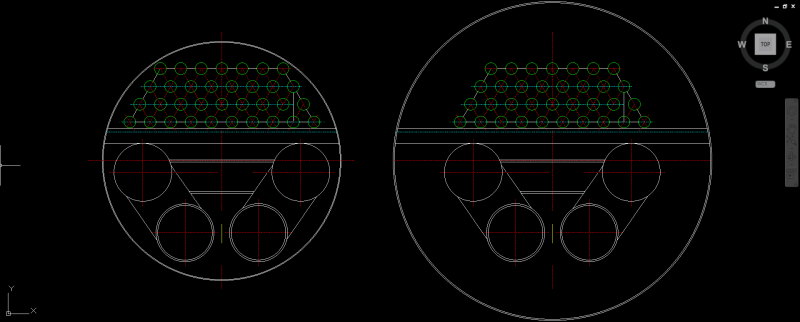
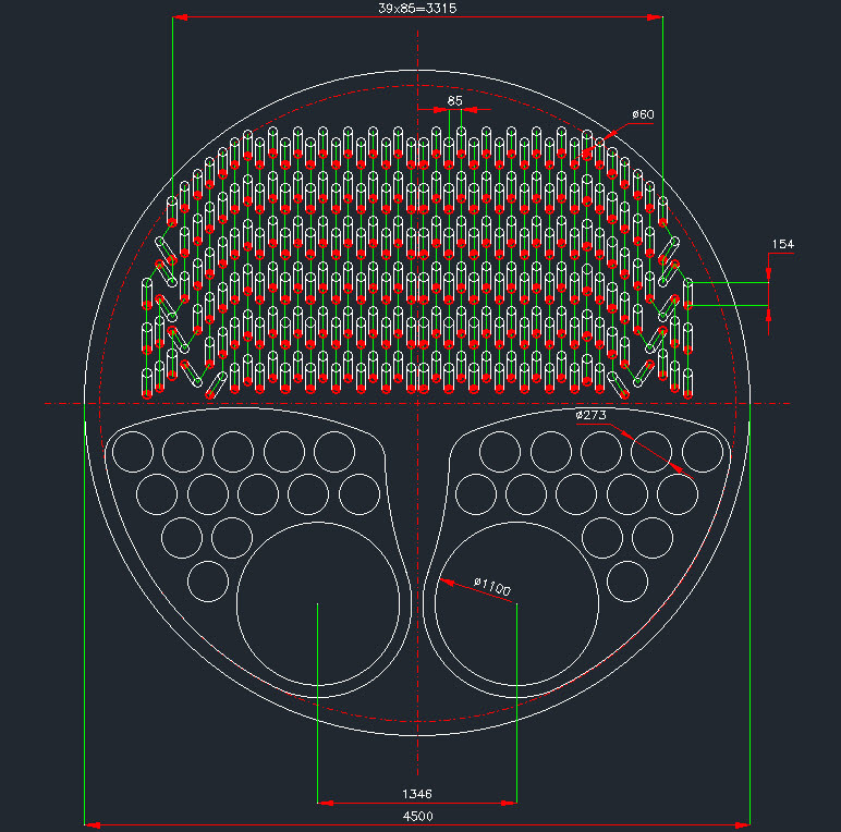
These are API 12K water bath heaters, not API560 heaters. The larger of the 2 would be the right selection; liquid height should be no more than 80% of vessel diameter. So you've got 2 U firetubes here. And the upper bank of tubes are the process fluid coils.
API 12K heaters have a thermal eff of around 60-65% max on fuel gas LHV, since there is no convection bank. There are limits on the max permissible heat transfer rate (ie Btu/hr/ft2) of external surface, and another on max permissible heat rate per unit cross section ( Btu/hr per ft2/ft) - I dont remember these values now; its a long time since I worked on API 12K heaters. But you can work these numbers out from first principles. For the second of these limits, a max external surface film temp of say 95degC at the hot end of the firetube would be preferable to minimise evaporation losses, but many suppliers tend to ignore this important limit in the interest of low capital cost. Also look for these limits in API 12K and other books such as Campbell's Gas Conditioning Handbook or the GPSA. Thermal design for these is much simpler than API 560 fired heaters. You may have to select a forced draught unit for safety reasons (as opposed to legacy induced draught units which have a higher risk of flashback) but at higher cost.
Centre to centre pitch for the firetube elbows and for each process bend may be found from piping data on standard SR elbows. And use the same gap for distance between elbows. LALL for the water should permit some say 100-150mm submergence of the highest row of process tubes.
Think what you should be working on is the fuel gas hydrocarbon dewpoint, not the dewpoint of the fuel-air mix. Use a process simulator - Hysis-Aspentech or Pro-II/Simsci.


Hello folks!
I have been working on another project and couldn't come here and continue the discussion. Now, I have reached an arrangement consisting of two furnaces and thirteen return fire tubes. The general duty of the heater is 10 MW. The heater follows a natural draft circulation. I want to put four burners into each furnace to gain the task. Is it possible?
2023-05-04_12-16-46_rifxat.jpg
 
Status
Not open for further replies.
Back
Top