Continue to Site

Eng-Tips is the largest engineering community on the Internet

Intelligent Work Forums for Engineering Professionals

  • Congratulations SDETERS on being selected by the Eng-Tips community for having the most helpful posts in the forums last week. Way to Go!

Induction Coil Design

Status
Not open for further replies.

ABrown123

Mechanical
Jan 31, 2017
2
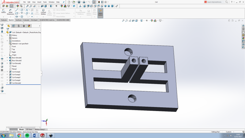
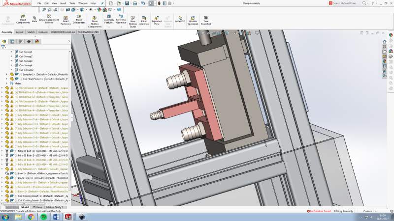
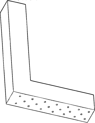
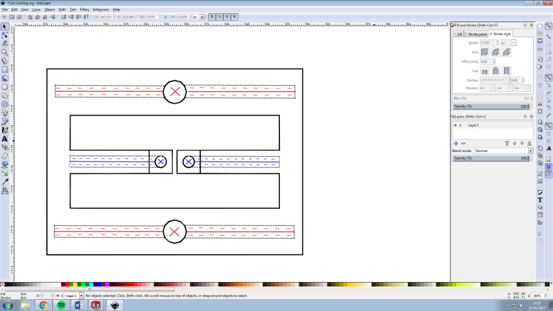
I am designing an induction heating rig to heat a strip on the surface of a steel sample with repeated quenching, through holes in the heating surface of the coil (shown in the third image)

Firstly, could anyone comment on the current coil design (split-return rectangular copper pipe)
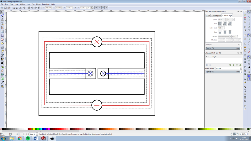
Secondly, there are two options for cooling, as shown in the image, one which quenches the sample from the centre leg and one which does so via the centre and return legs. Would the coil get too hot if it was only cooled during the quench cycle (half of the time) as in the second image?

Thanks in advance
Coil_fqztxh.png

Coil_in_assembly_hy07ze.png

Centre_Leg_Quenching_wpyybj.png

Coil_Water_flow_aigczv.png

Coil_Water_Flow_2_tqcqox.png
 
Replies continue below

Recommended for you

I was a dumb kid, helping out with axle scanners, fifty years ago.

WRT your last question, I'd expect your coil to melt, instantly, absent cooling water flow.

WRT mine, I could swear the cooling water flow was separate from the quench water flow.
I think the cooling water was recirculated, and chemistry controlled.
... or both flows may have been the same water + soluble oil that was used for cutting tools and recovered via flumes in the floor.

It was a long time ago.


WRT less ancient experience with power transistors, I wouldn't expect the current to divide symmetrically in your 'split return'. If you've done it for years, just ignore me.


Mike Halloran
Pembroke Pines, FL, USA
 
Thanks for the advice.
Re melting, I was worried about that, hopefully the first water flow diagram would suffice to remove enough heat from the coil?

I have toyed with having two flows for quenching and cooling like you mentioned, unfortunately the wall thickness is already nearing the skin depth (this coil is only 10mm deep)

Im aware of the unsymmetrical current splitting, this shouldn't be an issue, its the centre leg that does all the useful work.
But regarding experience, this is my first time designing a coil past simple helical ones, i really have no idea!
 
The coils on our axle scanners comprised a copper tube helix of about two turns.
The electrical and fluid terminations were via two humongous copper plates, to which the coils were brazed. The plates bolted to fixed and electrically isolated manifolds, with o-ring face seals.
The quench flow was delivered by a brass donut, with the inner half pierced in many places.
There were some thick FRP spacers between the donut and the coil, and between the induction coil turns, epoxied in place, to keep the (substantial) magnetic forces from deforming the coils.
The assemblies cost several thousand dollars apiece, when that was a _lot_ of money.
The coils didn't last long, but we were producing a lot of axles.


In your design, I'd be worried about the small thermal mass around the electrical terminations, and all the sharp corners. Perhaps you have saved the fillets and radii for later in the design stage, or rolled back past them (and dielectric spacers between the vertical legs) for the screenshots.


Mike Halloran
Pembroke Pines, FL, USA
 
Status
Not open for further replies.

Part and Inventory Search

Sponsor