Eng-Tips is the largest engineering community on the Internet

Intelligent Work Forums for Engineering Professionals

Induction heating. Low tq thyristors 2

Status
Not open for further replies.

Skogsgurra

Electrical
Mar 31, 2003
11,815
0
0
SE
Self-commutated H bridge. Running at 400-600 Hz with DC up to 2 kV and output current up to 1 kA.

The original design uses three thyristors in each "leg" of the H. The reason is that fast thyristors were not available at 2 kV at the time of its conception and birth.

It seems to be time to refresh this granddad and give it better legs where a single thyristor handles each leg. That would make things a lot simpler (four thyristors instead of twelve) and make it less sensitive to snubber and voltage divider problems.

The I[sub]gate[/sub] is standard, couple of volts and 1-2 A. Nothing special there. The t[sub]q[/sub] is where the problem is. Tests have been made with long t[sub]q[/sub] (like 200 us)and with no luck.

Been searching the Net for some time but don't find anything suitable. Any tips from EngTips?

Gunnar Englund
--------------------------------------
Half full - Half empty? I don't mind. It's what in it that counts.
 
Replies continue below

Recommended for you

Hi Gunnar,

It's been a while since I was playing with inverter-grade thyristors, but Westcode used to be my go-to supplier for fast thyristors. They're part of IXYS now - did you see this range of thyristors? The t[sub]q[/sub]'s are low for their ratings: Specifically the gets you to a t[sub]q[/sub] of 40[μ]s or less with 2100V and 1700A rating, depending on whether the other properties are acceptable.

I haven't used Powerex for inverter-grade stuff, only their very large power frequency types. A quick look on their website brought up and
 
Thanks Scotty!

That link gave a much better overview than I found during my futile attempts at finding the corresponding information. We will look deeper into those possibilities. Much deeper.

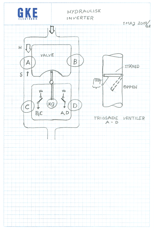
I am dealing with mechanical people and it has been a challenge to make them understand how the inverter works. I then made a "hydraulic" drawing (no standard symbols were used) to tell them what happens. It worked very well and they seem to understand it all. Looking forward to next meeting.

Gunnar Englund
--------------------------------------
Half full - Half empty? I don't mind. It's what in it that counts.
 
Sparky to Clanky:

Nordic_Ferro_Alloys_hydraulisk_inverter_1_yl1nbj.png


H is main flow/current S is reverse flow/current

If flap doesn't close in time, it will stay open and the fastest valve (IRL, there are three in series in each leg) will take all the pressure/voltage. Which it isn't designed for.

The vane is the furnace oscillating like a pendelum between positive and negative voltage and triggering the release coils for A,D and B,C when limit switches are hit.

Gunnar Englund
--------------------------------------
Half full - Half empty? I don't mind. It's what in it that counts.
 
That's very good Gunnar, a hydraulic oscillator.

I had actually envisaged the three thyristors in parallel to boost the current rating, not series for increased voltage rating. Paralleled devices are still fairly common today in very high current applications like static exciters for large generating plant as I'm sure you know. How did the designers handle the voltage division across the thyristor stack - or does it just rely on close matching of the three devices and hope for the best?
 
It has the look of a current-source design with a near-resonant load. That strikes me as quite a brave circuit design - device matching looks fairly critical to operation. I can understand the desire to move to a single switch in each leg.
 
Thanks, iop. But we are a little bit beyond that stage. The discussion is about t[sub]q[/sub], withstand voltage and voltage distribution when employing several thyristors in series etcetera. I'm saying this so we don't get the thread cluttered with lots well meant but rather out-of-place "tips".

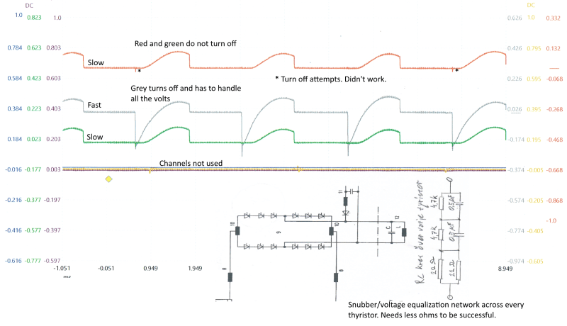
If you look at the wave-forms and read the comments, you may notice that the failure to turn of two of the three series connected thyristors is because they are much slower (around 200 us, than the "grey" one. The grey one turns off (in 20 us) the way it should and, doing so, gets exposed to a voltage that should be dealt with by all three thyristors in series. The current then drops to near zero so that there is no reverse current left to turn the still conducting (red and green) thyristors off. Semiconductors have improved over the years and we are now planning to use four 2 kV thyristors instead of 12 (three series connected/leg) thyristors with lower V[sub]DRM[/sub]. That is what the thread is about and that is also indicated in the subject line.

Gunnar Englund
--------------------------------------
Half full - Half empty? I don't mind. It's what in it that counts.
 
Right! It is a Monte Carlo/Las Vegas situation.

That's why the snubbers have rather low series resistance and why there are parallel resistors for even voltage distribution. The design is old. Drawings are dated 1977, so it is about time to improve the whole thing.

I must say that it is a good design, for that time. It ran without problems till 2016.

Gunnar Englund
--------------------------------------
Half full - Half empty? I don't mind. It's what in it that counts.
 
My mistake... in the first post you were talking about a 200us test that did not work and I thought the waveforms already refer to the modified version ... with a single thyristor on leg.
Such a big difference in tq, 1:10, is normal to lead to blocking the fastest.
Regarding this statement: "Tests have been made with long tq (like 200 us) and with no luck.", do you made tests with one 200us thyristor on a leg and fail to turn-off? If yes, maybe need to check dv/dt conditions/capability.
 
OK. I see.

I wasn't there when the fail occurred, so there are no recordings from that.

The recording shown is when running at a reduced DC voltage. Low enough not to cause another fail. It shows that the fastest thyristor does what it is supposed to do and that the slower ones start to turn off. But no current "left" to do that properly.

New tests with other thyristors are planned within a few weeks. There is one furnace running. It has the 20 us thyristors in all positions. The problem is that the buying people had no idea what was actually needed and seem to go the easy way - buy the cheapest. Seen it too many times. I wish they would let the people that know what is needed do the procurement. But, no. MBA:s are slowly ruining the industry. There's more to life than Business Administration...

Gunnar Englund
--------------------------------------
Half full - Half empty? I don't mind. It's what in it that counts.
 
Do you have some details regarding firing control?
For such IH inverter with variable freq in 400-600Hz range, most probably use auxiliary thyristors with LC circuits to control turn-off.
With new 20us thyristors I think must modify timing for aux thyristors and LC circuit if any.
 
Thanks for your interest. But if you care to look at wave-forms and the diagram below them, you will see that this is an H bridge where thyristors are commutated by turning on the other (diagonal) pair of legs.

Also, please note that this is a 40 years old plant that works OK as long as one doesn't try to save money by buying slower thyristors.

Re gating pulses: They are between 18 and 20 us wide with around 2.5 A amplitude and risetime in the order of 500 ns when measured with a 20 MHz DC clamp. No need to change anything there. And no need for auxiliary turn-off thyristors with the associated LC circuit or using GTO:s. The bridge is, as said, self-commutated.

The original question was mostly about finding thyristors that can be used. That question was answered to great satisfaction by ScottyUK and we really do not need any more inputs regarding this.

Gunnar Englund
--------------------------------------
Half full - Half empty? I don't mind. It's what in it that counts.
 
If you've lost the turn-off sharing then the old devices likely had the Qrr or Ir matched and that requirement has been lost with the replacements. Properly matched devices don't require a huge amount of snubber for successful series operation.

I can't see 2000V SCR's being suitable for a circuit that operates at 2000V. You found some suitable 4000V or more rated devices to use?
 
No, I don't think there are any such devices readily available. I live only around 20 miles from the ABB HVDC center in Ludvika and I am sure they have a few HV devices. But they are used in mains commutated 50/60 Hz applications and I don't think they can be used for a lot of other reasons as well. Dimensions, cost, current range (guessing) and ABB not being willing to sell are a few of them.

There is already a limit with the three devices/leg. The DC source has been limited to run lower than 2 kV and we are discussing if it is better to have a safety margin than to run at maximum capacity.

In my view, there are six series connected devices. Three in each leg. And the measurements we have made so far seem to show that the voltage distribution is such that each leg takes half the voltage. That would make 2 kV devices fit the bill. Time will show. No activity planned before we get the devices. Still have to decide what to use and then there is delivery time. It is not only I that decide. I am the "Messknecht", so to say.

Gunnar Englund
--------------------------------------
Half full - Half empty? I don't mind. It's what in it that counts.
 
I think it's there an aux circuit made by a LC group and a SCR (near number 11); this one made turn-off.
As new Tq is around 10 times smaller, need to modify this LC circuit to increase 10 time resonant freq.
If no big Qrr difference between old/new SCRs, C must remain around and L decrease about 100 times.
 
No, iop. That is the precharge/starting circuit. I know that you mean well. But your tips are of no use here. Really not.

Gunnar Englund
--------------------------------------
Half full - Half empty? I don't mind. It's what in it that counts.
 
Status
Not open for further replies.
Back
Top