Continue to Site

Eng-Tips is the largest engineering community on the Internet

Intelligent Work Forums for Engineering Professionals

  • Congratulations IDS on being selected by the Eng-Tips community for having the most helpful posts in the forums last week. Way to Go!

Induction Motor Torque 1

Status
Not open for further replies.

bohdand

Electrical
Dec 18, 2006
20
Hi,

I have a unique question on what is the torque on a motor shaft if it is started while already spinning at full speed, but in the opposite direction. The real world case I am trying to analyze is: a pump storage hydro generator (38MVA synchronous machine with a squirrel cage winding on the rotor) is brought up to speed no load (SNL) by the water wheel with no excitation and then connected to the utility system BUT, the system phase rotation is opposite that of the generator. My question is what is the torque that would be produced on the motor/gen shaft?

The machine is a synchronous generator that is designed for induction starting in the pump mode and has a set of shorting bars embedded in the face of the rotor poles (squirrel cage design). Since the machine has no excitation I see this as a 3 phase induction motor and I am using the Torque equation to calculate torque. The equation I am using is:
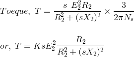
torque-equation-of-three-phase-induction-motor-21_es03qt.gif


Where

T=torque
s=slip
E2=rotor voltage
R2=rotor resistance
X2=rotor reactance
Ns=synchronous speed

and

s=(Ns-N)/Ns

Where
N=rotor speed

What I do is I substitute in a negative N into the slip equation, get a slip of 2 and substitute into the Torque eq. Assuming that R & X are small relative to E, that would make the Torque much higher that a locked rotor torque.

I'm not sure if I am doing this right and was hoping that the guru's could chime in.

Note: This will not happen since proper phasing checks will be done first, but the question of what would happen if this were to happen came up.

Thanks,

Bohdan
 
Replies continue below

Recommended for you

I'd like to understand the sequence better.
Beginning with the state of machine spinning at rated speed, no rotor or stator excitation.
Then you're going to close the stator breaker?
At this point the rotor field poles are still open circuited so I think there is no torque associated with the field poles, but you have a torque from the induction effect in the shorting bars.
That's the torque you are trying to predict?
Are these equivalent circuit parameters R2, X2 and E2 associated with the shorting bars?
I would expect it would be slightly less than the torque which would occur if the stator was energized at full voltage (with rotor poles open circuited) while at standstill. If this is your induction starting scenario (full voltage) then I don't think the torque will be any higher. There is also a question of the heating pattern (more skin effect).

=====================================
(2B)+(2B)' ?
 
Did you run the calculations with 200% slip? If you did, then what result did you get?
 
The torque should be slightly lower than locked rotor torque, as Pete says.

The reason is that you have a higher reactance in the rotor amortisseur winding at 120 Hz (or 100 Hz if in 50 Hz land) than you have at 60 (or 50) Hz. The higher reactance shifts rotor current more towards 90 degrees, which reduces torque.

Of course, if you have a very resistive winding - your torque will be higher. You need real world data plugged in to see if that is so.

Gunnar Englund
--------------------------------------
Half full - Half empty? I don't mind. It's what in it that counts.
 
The basis for my previous comments is the equivalent circuit. My post 28 Apr 11 08:39 in this thread: thread237-296725 provided an equivalent circuit discussion of why there is a monotonic increase of torque with speed at speeds below the speed of breakdown torque (Or translating it to the current thread: a monotonic decrease of torque with slip at slips above breakdown slip.). One assumption of the equivalent circuit model in this proof is that the values R2 and L2 remain are constants.

But I missed some things:

1 - What may be different in the real world - one of the assumptions is that R2 and L2 remain constants - does not account for any change with frequency. If there is a deep bar or double cage it will be a big effect. Apparently it is the case for some synchronous machines.

2 - The rotor field windings are not open but instead short circuited by the field discharge resistor (I was wrong to say it was open circuited)

I discovered (or remembered) these items by reviewing a link:

On pages 10-12 you will see a qualitative discussion of torque speed curve for a particular synchronous machine from 0 to sync speed. We might suspect that if we project the curve to the left of the vertical axis (negative speed) we get an idea of what the torque might be for negative speeds.

Some highlights from that link:
Page 10 lists 5 components of torque, with only the first two significant
1. Amortisseur windings (shorting bars)
2. Field windings (short circuited by field resistor)
3. Hysteresis in pole faces
4. Eddy currents in pole faces
5. Variation in magnetic reluctance

A plot of torque from item 1 (Amortisseur windings) is shown at bottom left of page 11. For double cage rotor the total torque is increasing as you go to the left past the zero speed vertical axis.

A plot of torque from item 2 (is shown at bottom of page 12). The torque is decreasing as you go to the left past the zero speed vertical axis.

We might guess that if you add all these together for this machine is still decreasing as you go to the left and will be lower at a negative speed. But it is qualitative and guesswork and your machine may be different. Equivalent circuit won't provide any definitive answer without understanding change of R2 and L2 vs frequency.


=====================================
(2B)+(2B)' ?
 
The current will be high and the torque will probably be less than breakdown torque.
The time to stop the motor will probably be equal or greater than the time to accelerate a cold motor from stop.
A rough assumption may be that the torque and current will be near locked rotor values.
Now when we plot this we see that to the right of the 0 RPM line we have high values decreasing to normal.
To the left of the 0 RPM line we have high values for a time equal to or greater than the normal acceleration time.
The I2T may easily be equal to the heating of several starts before the motor is brought to a stop.


Bill
--------------------
"Why not the best?"
Jimmy Carter
 
You may want to do a search on the "plugging" of induction motors, which is essentially what you are doing here. People have used plugging for relatively quick stopping of a motor, implementing it by swapping the connection of two of the leads, thereby reversing the direction sense of the AC input.

Of course, most of the people plugging a motor just want to stop it. It appears you want to go (roughly) from full speed one direction to full speed in the opposite direction.

Curt Wilson
Omron Delta Tau
 
I remember those old "U" frame motors. Plugging reversing and plugging to a stop.
We quit doing much plugging when the industry transitioned to "T" frame motors.
The torque at various slip frequencies depends on the rotor design, mostly on the profile, depth and resistance of the squirrel cage bars.
Your machine may have excellent torque characteristics or if may have marginal performance.
Remember, an induction motor has current flowing in the squirrel cage winding all the time.
In a synchronous machine, there is no current in the squirrel cage when the machine is at synchronous speed.
This may influence the design in regards to heating of the rotor.

Bill
--------------------
"Why not the best?"
Jimmy Carter
 
Thank you all for your insights. Here are some answers to the questions raised (unable to get to this till this morning) that may shed some more light:

electricpete - the R2 X2 in the equation refer to the shorting bars only. Since this equation only applies to a standard induction motor, then it does not account for the field poles/windings. When this machine is started the field is shorted across the leads through a 2.25 Ohm resistor (not a discharge resistor). I was unable to open your link.

waross/Skogsgurra - the squirrel cage winding in this machine is specifically designed to have high starting torque (bars are brass with a resistivity of 68 Ohm-cmil/ft and not pure copper) with an rough estimate of 6,000 amps through each bar during starting (based on vendor modeling). The bars are a mix of 5/8" and 3/4" brass bars with the bar center embedded about 1" into the face of each pole (rotor diameter about 13'). This is a 13.8kv, 38MW motor/38MVA vertical design hydro generator - salient pole. The shorting bars are designed for one start per hour due to the heating effects.

I had not considered the effect of frequency on the reactance value. Looking at the torque equation, the X in the denominator will be twice as large (120 vs 60) which would reduce the torque?? Does using a slip of 2 allowed in this equation?


I was unable to open your link.
It works for me:
It is a pdf so of course you need a pdf reader plugin for your browser (or else try to download the file by right-clicking on the link and then view it from your hard drive)
Also perhaps try to access it directly from google. For me it is the first result when I google the following: The ABC’s of synchronous motors - WEG


=====================================
(2B)+(2B)' ?
 
That opens for me, Pete.

Bill
--------------------
"Why not the best?"
Jimmy Carter
 
Thanks Bill. I agree with you the I^2*t integrated heating is much more likely to be a challenge than the torque.

=====================================
(2B)+(2B)' ?
 
We used to see this in submersible pumps, they would trip off and fluid in the outlet line (12,000' vertical) would start flowing back, and then someone would try to turn the pump on. We had voltage sense interlocks to prevent it but sometimes they would override them.
Every time this would break a shaft. All shafts and couplings would handle at least 1.25x max motor (locked rotor) torque, but trying to start one turning in reverse would break things. This may have been an artifact of the design.
These were small diameter (under 6") motors that were typically 20' long and wound for high voltage low current.

= = = = = = = = = = = = = = = = = = = =
P.E. Metallurgy, Plymouth Tube
 
Yes, good point. You and others have discussed the potential for damaging mechanical torques in the train when energizing a motor from reverse rotation in this thread thread404-411251

We as electricals have a better handle for the EM torque generated by the motor. If EM torque doesn't get any higher than locked rotor torque (plus a transient component due to dc inrush current, similar to normal start), then it's not clear why components of the train would see any higher torque during start from reverse rotation than they do during a normal start (passing through torsional resonance is a possibility in either scenario). You and others say it occurs, I can't dispute that experience. But the mechanism remains a mystery to me.


=====================================
(2B)+(2B)' ?
 
I believe that a lot of it has to do with the stiffness of the system. Our systems were long (80-130') and whippy. At running load the bottom of the shaft (bottom of lower motor) was about 2 full revolutions ahead of the top of the upper pump. That is a lot of stored energy, and that would contribute load above the FLR value.
With a short stiff system the impeller would likely have a very high momentum (large dia). I could see this burning a motor up while it was trying to stop it.

= = = = = = = = = = = = = = = = = = = =
P.E. Metallurgy, Plymouth Tube
 
Thanks Ed. I appreciate that response, and highly respect your opinion.

But I still don't quite get it.

We consider the long shaft as a torsional spring.

If we start from rest, the torsional spring is initially unstretched.

If we start from reverse rotation at a steady state speed, then the torsional spring is again initially unstretched for all practical purposes (it only has enough strain to transmit the torque associated with overcoming friction to keep the motor operating at constant speed).

The only difference that is obvious to me is that there is a wider range of speed to accelerate through… can't see where there is a higher peak torque.


=====================================
(2B)+(2B)' ?
 
Pete:

Many years ago, when I went to understand the operation of induction motors from first principles, I got a result that showed that startup torque was always lower than low-speed torque and that torque steadily increased with speed (decreasing slip) in the startup range.

But I saw from real-world curves that many induction motors have higher torque at zero speed ("locked-rotor torque") than they do at somewhat higher speeds, where the torque hits a minimum -- called the pullup torque value. In those pre-internet days, I had no explanation for it, so it took me a long time to find the reason.

The key reason for this behavior is "skin effect", which causes the resistance and inductance of the rotor bars to vary with electrical frequency. If a motor is designed to exploit this effect, the torque gets greater at slip values greater (velocities lower) than that of the pullup torque.

Common torque-speed curves only go down to zero velocity, but from the slope of the curve at zero velocity it is obvious that the torque will keep increasing for slip values greater than 100%.

I am far from an expert in motor design, but it seems to me that this is a reasonable explanation for the problem reported.

Curt Wilson
Omron Delta Tau
 
The other factor to consider is the momentum of the water column in the pipe and how it interacts with the impeller. The purpose of the impeller is to spin water to give it momentum (velocity). With no flow through the pump, water just spins in place and there is low load on the impeller. But the spinning water does generate pressure, which will slowly accelerate the water column after the pump. As water starts to flow, more non-spinning water enters the pump and has to be accelerated, thus increasing load on the pump. I just described the normal operation of the pump.
Now if water is flowing back through the pump from a 12,000 ft. vertical pipe all the water in the pipe has to stop before flow can reverse. I imagine that since there is no check valve this reverse flow rate could be many times forward flow rate. So water will continue to flow back through the pump for a considerable time even after the pump starts, perhaps at several times the rated flow of the pump. The pump and motor will certainly be overloaded, more so than if the pump was just stuck with a rock in it.
 
Thanks curt. Yes, the skin effect is a refinement I discussed 5 Jan 17 15:32.

A qualitative figure here (the first figure = Figure 6.15):

In this particular figure the torque at s=2 goes a lot higher than locked rotor but not quite as high as breakdown torque (mileage may vary for other motors).

You're right, maybe it explains (or contributes to) the snapping shaft/couplings thing. Especially if the dynamics at start are different than the dynamics when passing breakdown torque. Or fluid momentum mentioned could play a role in Ed's pumps (even though doesn't apply to the generator scenario or the fan scenario from the linked thread other thread). I can't piece it altogether but I agree the higher torque at start with s=2 could be a big factor.

I should circle back on this question.
bohdand said:
I had not considered the effect of frequency on the reactance value. Looking at the torque equation, the X in the denominator will be twice as large (120 vs 60) which would reduce the torque?? Does using a slip of 2 allowed in this equation?
You could only substitute s=2 into the equation with confidence if you knew that X2 and R2 are constant. They may not be with deep bars due to skin effect. Also as you mentioned these equivalent circuit values may not reflect current in rotor windings through whatever resistor is shorting it.


=====================================
(2B)+(2B)' ?
 
I had not considered the effect of frequency on the reactance value. Looking at the torque equation, the X in the denominator will be twice as large (120 vs 60) which would reduce the torque?? Does using a slip of 2 allowed in this equation?
Let me add a little more.
X2 is an equivalent rotor leakage reactance referred to the stator side.
You could write it the following way
X2 = 2*pi*F * L2(slip)
Where:
F is the ac stator supply frequency (it doesn't change, regardless of speed or slip...it doesn't change when rotor slip frequency doubles as you implied)
L2(slip) denotes that L2 varies with slip (can increase due to deep bar effect as s approaches or exceeds 1).
You also need to write R2(slip) to denote that R2 varies with slip (can also increase due to deep bar effect as s approaches or exceeds 1).


=====================================
(2B)+(2B)' ?
 
Status
Not open for further replies.

Part and Inventory Search

Sponsor