-
1
- #1
RattlinBog
Structural
Let me know if I should move this to the student section. I work full time at an industrial facility as an owner-structural engineer, but I'm also working on my M.S.C.E. part time. This post is technically about my plan B grad project, but I feel like it's relevant to any industrial structure design, too.
For my grad project, I'm working with my professor to take one of the large structural steel buildings at the place I work and design it from scratch with modern codes as a thorough exercise. Original structure was built in the 70s. My goal is to use the same overall building geometry but analyze and design it for ASCE 7-16, AISC 360-16, etc., and try to cover as many structural systems and components as I can--diaphragm, LFRS, purlins, girts, columns, floors, connections, foundations, etc. I'm trying to do most of the design by hand and only rely on software to double-check things. I don't have a lot of overall building design experience in practice (especially now that I'm in an owner role), so this project has been helpful to understand how individual components act together in a system, especially for lateral loads.
Would it be okay if I used this thread to ask occasional questions as they come up?
If so, here are some questions about diaphragms, purlins, girts, and eave struts. (I've read through and bookmarked several past eng-tips posts about this, but there are still a few questions in the back of my mind.)
Building info:
Ground snow load = 70 psf; basic wind speed = 107 mph
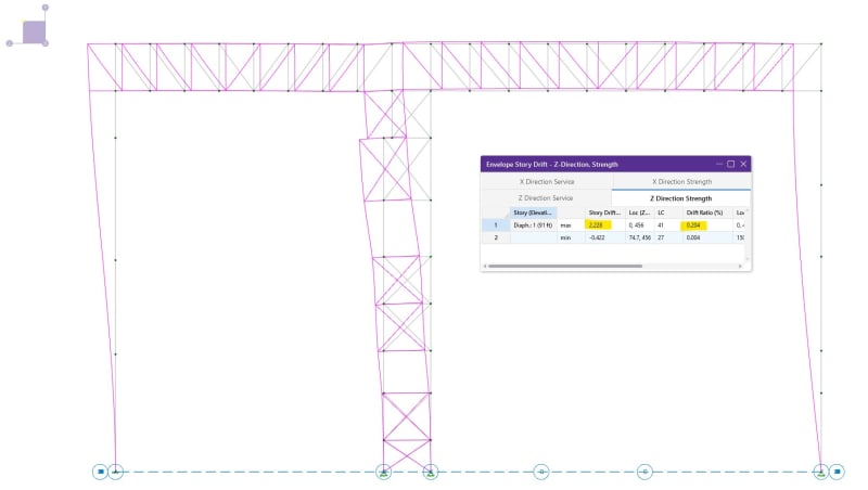
150 ft (north-south) x 456 ft (east-west) x 91 ft mean roof height.
Roof: purlins on trusses @ 24 ft O.C. (north-south)
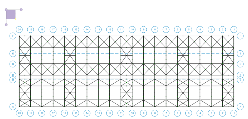
Diaphragm: horizontal brace system at bottom chord of roof trusses (assuming roof decking attached to purlins is not designed as a diaphragm)
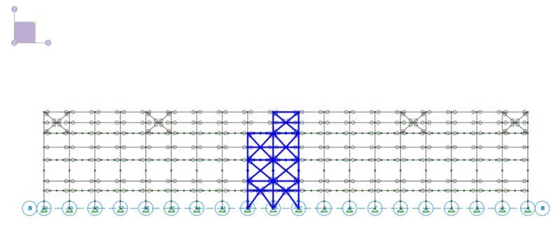
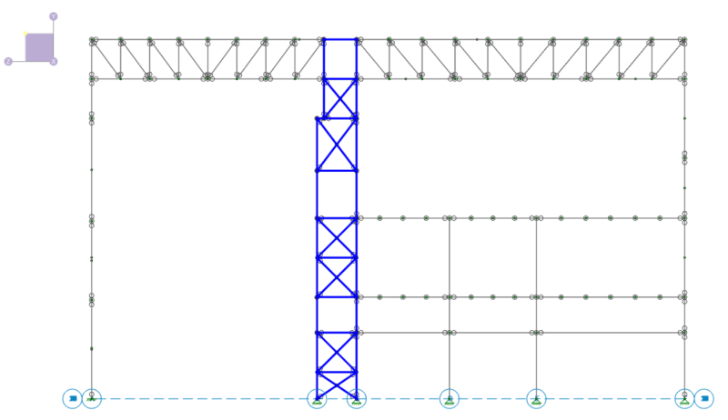
Lateral force resisting system (LFRS): 3 lines of braced frames (east-west); and built-up/braced cantilevered double column tower @ 24 ft O.C. (north-south)
Building is similar to a PEMB in that it's a massive structural steel frame with a lot of open space and no intermediate diaphragms, but all structural members are hot-rolled standard AISC shapes (no Z-girts or rod bracing, etc.)
Questions:
See attached calcs for purlin and girt design.
1. My understanding is cladding/roof deck will provide continuous lateral bracing for the exterior flange of girts and purlins for pressure wind loads. For suction/uplift wind loads, sag rods will provide discrete lateral bracing to the interior flange by preventing twist through a resistant force couple with the cladding/roof deck. Is that what others have seen? (I saw some eng-tips members from Australia and Europe mention bridging instead of sag rods, but I haven't come across that in the buildings I've seen locally.)
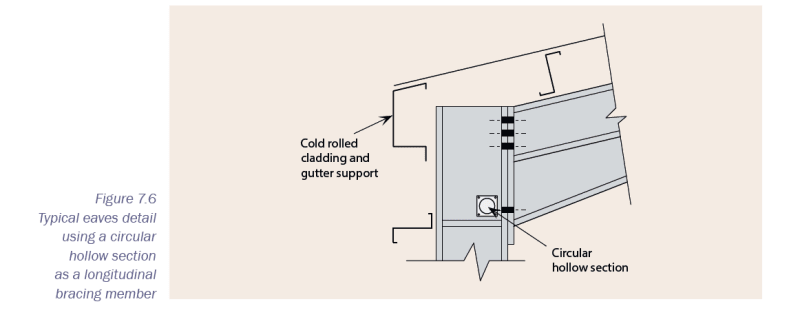
2. Is cladding dead load typically picked up by the eave strut through sag rods in tension? My understanding is that girts (assuming channels) are not designed for gravity loads in weak-axis bending and are only meant to resist wind loads in strong-axis. The gravity loads (cladding) are brought up from the girts to the sag rods to the eave strut.
3. Is metal roof deck typically ignored for diaphragm design in large industrial buildings? That's been my assumption so far, and I'm only relying on the horizontal plane bracing in the roof to bring lateral loads to my LFRS.
4. Are eave struts typically designed for both gravity (cladding dead load) and lateral (as a collector for bringing wind loads to LFRS) demands? Or is it better to have two separate members? Seems like two members might be warranted as the girts and LFRS bracing would be offset.
Thanks!
For my grad project, I'm working with my professor to take one of the large structural steel buildings at the place I work and design it from scratch with modern codes as a thorough exercise. Original structure was built in the 70s. My goal is to use the same overall building geometry but analyze and design it for ASCE 7-16, AISC 360-16, etc., and try to cover as many structural systems and components as I can--diaphragm, LFRS, purlins, girts, columns, floors, connections, foundations, etc. I'm trying to do most of the design by hand and only rely on software to double-check things. I don't have a lot of overall building design experience in practice (especially now that I'm in an owner role), so this project has been helpful to understand how individual components act together in a system, especially for lateral loads.
Would it be okay if I used this thread to ask occasional questions as they come up?
If so, here are some questions about diaphragms, purlins, girts, and eave struts. (I've read through and bookmarked several past eng-tips posts about this, but there are still a few questions in the back of my mind.)
Building info:
Ground snow load = 70 psf; basic wind speed = 107 mph
150 ft (north-south) x 456 ft (east-west) x 91 ft mean roof height.
Roof: purlins on trusses @ 24 ft O.C. (north-south)
Diaphragm: horizontal brace system at bottom chord of roof trusses (assuming roof decking attached to purlins is not designed as a diaphragm)
Lateral force resisting system (LFRS): 3 lines of braced frames (east-west); and built-up/braced cantilevered double column tower @ 24 ft O.C. (north-south)
Building is similar to a PEMB in that it's a massive structural steel frame with a lot of open space and no intermediate diaphragms, but all structural members are hot-rolled standard AISC shapes (no Z-girts or rod bracing, etc.)
Questions:
See attached calcs for purlin and girt design.
1. My understanding is cladding/roof deck will provide continuous lateral bracing for the exterior flange of girts and purlins for pressure wind loads. For suction/uplift wind loads, sag rods will provide discrete lateral bracing to the interior flange by preventing twist through a resistant force couple with the cladding/roof deck. Is that what others have seen? (I saw some eng-tips members from Australia and Europe mention bridging instead of sag rods, but I haven't come across that in the buildings I've seen locally.)
2. Is cladding dead load typically picked up by the eave strut through sag rods in tension? My understanding is that girts (assuming channels) are not designed for gravity loads in weak-axis bending and are only meant to resist wind loads in strong-axis. The gravity loads (cladding) are brought up from the girts to the sag rods to the eave strut.
3. Is metal roof deck typically ignored for diaphragm design in large industrial buildings? That's been my assumption so far, and I'm only relying on the horizontal plane bracing in the roof to bring lateral loads to my LFRS.
4. Are eave struts typically designed for both gravity (cladding dead load) and lateral (as a collector for bringing wind loads to LFRS) demands? Or is it better to have two separate members? Seems like two members might be warranted as the girts and LFRS bracing would be offset.
Thanks!