Continue to Site

Eng-Tips is the largest engineering community on the Internet

Intelligent Work Forums for Engineering Professionals

  • Congratulations SSS148 on being selected by the Eng-Tips community for having the most helpful posts in the forums last week. Way to Go!

Industrial steel building joint detail 1

Status
Not open for further replies.

kobzarev_92

Structural
Oct 5, 2022
5
Dear all,

I'm starting this thread in search for infos about a problem I encountered while reading a passage from N. Subramanian "Design of steel structures". The book is really detailed and explains well the basics (and even something else) of steel structure design, however I found a non really clear passage that I want to share with the community, hoping to find an answer. The first attached image deals with braced frames structure type. In the above mentioned passage it is stated that at the bottom chord of the frame (under tension in normal DL+LL condition), there will be a truss frame in order to collect horizontal loads to be transmitted to the gable ends bracings. While it is clear the use of the truss frame, I found some difficulties in finding a good joint detail solution like the one indicated as "Joint n°1". I didn't really find any useful infos around the web with a detailed sketch of how a similar joint could be done. Just to be clear, I'd like to know if someone could suggest how a joint in that situation could be done, containing the truss/wind column, the "eave strut" at bottom chord level, the diagonal in the bottom chord and the bottom chord itself. My concern is to have a joint that really replicates the physical behavior of a truss frame under horizontal loads, avoiding other internal forces to be transmitted.

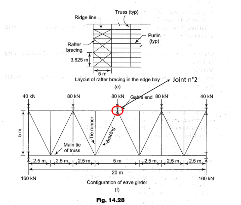
Same goes for the second attached image, where I indicated the "Joint n°2". However in this case the truss frame is used in the gable ends to collect horizontal loads to be transmitted to the longitudinal side bracings.

Thanks in advance for any answer!
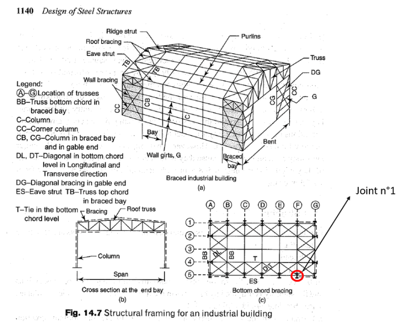
1_slspzo.png

2_ymtgya.png
 
Replies continue below

Recommended for you

You need to get yourself a copy of Design Guide 29 from AISC. If you're a member, it's free. Otherwise, it's $60, I think.
I think your question is regarding the combined tension forces plus gravity forces. On the east coast of the US, apparently it's common to post the forces on the connections and the steel fabricators delegate the design to a connection specialist. West of the Mississippi, it's not as common, but it can be done. Overseas, I don't know.
 
Are you a student? This forum isn't meant for students there is another forum for that.

I would add that if you are a student with limited or zero real world experience with steel then I think your question is fairly astute. Which is more than can be said for many people asking 'simple' questions in this forum. Go have a wander around a local warehouse or big box store or whatever is available in your area. Follow the load paths. You can learn plenty just by looking up.
 
JedClampett said:
You need to get yourself a copy of Design Guide 29 from AISC. If you're a member, it's free. Otherwise, it's $60, I think.
I think your question is regarding the combined tension forces plus gravity forces. On the east coast of the US, apparently it's common to post the forces on the connections and the steel fabricators delegate the design to a connection specialist. West of the Mississippi, it's not as common, but it can be done. Overseas, I don't know.

Hi Jed, thank you for the suggestion. I was wondering if I could find something on specific books that cover only joint design, however from my library I wasn't able to find any useful yet.

I think I'll take a look at the one you mentioned.

human909 said:
Are you a student? This forum isn't meant for students there is another forum for that.

I would add that if you are a student with limited or zero real world experience with steel then I think your question is fairly astute. Which is more than can be said for many people asking 'simple' questions in this forum. Go have a wander around a local warehouse or big box store or whatever is available in your area. Follow the load paths. You can learn plenty just by looking up.

Hi human, I didn't know I had to specify my job or my years of experience... I figured out posting on a professional forum was quite enough! [bigsmile]

That said, my experience on steel design is primarily linked to structures inside an industrial building, i.e. the ones used to support, for example, automatic production lines for automotive field.

Only in the last few months I had to pleasure to start focusing on the structure of an industrial building... I had to study and read some books, especially about the joint design that is, in some cases, different about the one I usually do when designing structures inside a building.

That is why I hoped some fellow professional structural engineer could give me some tips on the matter, especially if is someone with more experience than me.

In any case, thanks for the reply even if it isn't really an answer to that particular question! [smile]
 
GeorgeTheCivilEngineer said:
Do you just want to know how all the steel members physically meet at a node?

I found a document that maybe can better explain what I mean. In the below image there's a node with an horizontal bracing system, with 3 beams and a column. That is, probably, the closest idea to my original post.

I was wondering if a similar system can be applied too, ensuring the truss frame only transmits normal forces between its members.

The only thing I'm not really sure about are the longitudinal beams, i.e. the "eave strut" at bottom chord level. I don't know if, to ensure the correct behavior, they should be placed like a wall girt (in the exterior side of the column, where the flange is) or inside the column space between the flanges (connected to the web).

1_lyfoeb.png


robyengIT said:
some useful info here, too

Thanks, really appreciated.

I did a rapid check on the last two suggestions and, even if there isn't the proper answer, I could see they have a lot of useful infos.

I couldn't find, however, the first one suggested... maybe I'm bad at researching things [ponder][bigsmile]
 
Mr kobzarev_92 (Structural),

I have old version of the book N. Subramanian "Design of steel structures". Apparently the picture that you mentioned is for definition of terms . I would prefer to extend the columns to the top chord level of the roof trusses.

Your internet country code (IT ) implies EC is applicable standards in your country.

I will suggest you to look to the following docs.


HTURKAK said:
Mr kobzarev_92 (Structural),

I have old version of the book N. Subramanian "Design of steel structures". Apparently the picture that you mentioned is or definition of terms . II would prefer to extend the columns to the top chord level of the roof trusses.

Your internet country code (IT ) implies EC is applicable standards in your country.

I will suggest you to look to the following docs.

Hi HTURKAK,

I think the meaning of that image, in that particular context, is to suggest possible bracing systems in order to give stability to the structure due to the possible horizontal loads. It was strange at first place, for me, to see the truss frame at the bottom chord level to collect wind/seismic forces... I usually have seen that system to be a part of the roof bracing that give stability to the top compressed chord as well as collect gable end forces.

However what Subramanian suggests is that both compressive and tensile chord member of the truss system should be checked against instability problem, due to the reversal of actions.

He then uses this combined solution and then let the roof bracing to be checked against wind forces... but it's a bit confusing this part (if you have the book maybe you can check it too, the first example of the chapter, the second image I originally posted). He designs both the roof bracing and the eave girder (at the bottom chord member) to collect horizontal forces.

Like I previously said I've always seen the solution at the roof, with the column/wind column that transmits horizontal forces up there.

What do you think of the solution suggested by the book? Is it useful in some situations?
 
Hi kobzarev_92,

The solution proposed by the book is a valid , applicable solution. The local practice may change but IMO, the solution is an example to BAD DETAILING ..

I will prefer the trusses supported on the columns about the top chord level for simplicity of connections, stability during erection ( CG of the truss would be below the supports ) etc...


I will suggest you to look
Steel Designers' Manual (by SCI Buick Davison, Graham W. Owens )

and the following doc.

 
kobzarev_92 said:
Hi human, I didn't know I had to specify my job or my years of experience...
No you don't but we do get alot of students so it is no an unreasonable question. Though I do apologise that I asked it.

kobzarev_92 said:
In any case, thanks for the reply even if it isn't really an answer to that particular question! smile
Your question wasn't specific but so it could be answered with specifics. Though I did include an answer. FOLLOW THE LOAD PATHS that should lead you to where to locate the members most of the time.

kobzarev_92 said:
The only thing I'm not really sure about are the longitudinal beams, i.e. the "eave strut" at bottom chord level. I don't know if, to ensure the correct behavior, they should be placed like a wall girt (in the exterior side of the column, where the flange is) or inside the column space between the flanges (connected to the web).
The eave strut carries compressoion and tension load due to lateral loads including wind on the end bays. It would be normal to align this with the wall bracing that is also carrying the same lateral loads. And it would be normal to align these central to the column to avoid eccentricity in the vertical reaction loads produced by the lateral forces.

Like I said it is all about load paths. And when things don't meet in a nice text book node then ensuring eccentricity is minimised or otherwise accounted for.
 
HTURKAK said:
Hi kobzarev_92,

The solution proposed by the book is a valid , applicable solution. The local practice may change but IMO, the solution is an example to BAD DETAILING ..

I will prefer the trusses supported on the columns about the top chord level for simplicity of connections, stability during erection ( CG of the truss would be below the supports ) etc...


I will suggest you to look
Steel Designers' Manual (by SCI Buick Davison, Graham W. Owens )

and the following doc.

Thank you very much.

I believe as well to be a better solution the one you proposed, however it's good to know both ways are possible [smile]

human909 said:
No you don't but we do get alot of students so it is no an unreasonable question. Though I do apologise that I asked it.

I think I have to apologize too, maybe I was a bit rude and didn't catch the real meaning of your post.

human909 said:
Your question wasn't specific but so it could be answered with specifics. Though I did include an answer. FOLLOW THE LOAD PATHS that should lead you to where to locate the members most of the time.

Yeah, that is a really good advice!

Most of the time a lot of mistakes into designing a good structure come from a bad vision of the load paths between the members.

This will translate also into bad joint design with all the problems that come with... last thing everyone want, I believe [bigsmile]

human909 said:
The eave strut carries compressoion and tension load due to lateral loads including wind on the end bays. It would be normal to align this with the wall bracing that is also carrying the same lateral loads. And it would be normal to align these central to the column to avoid eccentricity in the vertical reaction loads produced by the lateral forces.

Like I said it is all about load paths. And when things don't meet in a nice text book node then ensuring eccentricity is minimised or otherwise accounted for.

The first image I posted probably is a little bit confusing (some flaws on great books are normals, after all). The eave strut is clearly the first purlin from the beginning of the roof eave and when is a part of a truss frame, as mentioned to collect horizontal loads, will be under compression. I believe the missing part is that using a truss frame at bottom chord level one should introduce another beam to act as compression member (aligned with column center like you said), that is obviously different from the eave strut.

Thanks for all the reply, I think I have now a better understanding of it.
 
Status
Not open for further replies.

Part and Inventory Search

Sponsor