Continue to Site

Eng-Tips is the largest engineering community on the Internet

Intelligent Work Forums for Engineering Professionals

  • Congratulations GregLocock on being selected by the Eng-Tips community for having the most helpful posts in the forums last week. Way to Go!

Inelastic Column Buckling hand Calc help

Status
Not open for further replies.

Burner2k

Aerospace
Jun 13, 2015
193
Hi,
In order to verify my FE Nonlinear buckling results, I decided to do a simple 1D column buckling analysis. Before I went ahead and do a FE calc, I wanted to have hand calc results in hand.

The geometrical, fixity conditions & material properties of the column are listed below:

Length of Column = 10 inches
Diameter = 0.8 inches
Area of Cross Section = 0.502 in^2
MI = 0.020 in^4
Radius of Gyration = 0.2 in

End Fixity Conditions = Simply Supported

c = 1

L/Rho = 10/0.2 = 50

Material of Column: 2024-T3 Extrusion (certain properties have been approximated)
Source: Bruhn Table B1.1

Ec = 10.7e6 psi

F0.7 = 39000 psi

Fcy = 40000 psi

n (Shape Factor) = 11.5

I initially calculated Elastic Critical Buckling Stress using Euler's Equation =(pi^2 x E)/(L/rho)^2

Fc = 42424 psi

Since this exceeds the Fcy, the buckling is inelastic. Substituting E with Et in the above equation to calc crit buckling sterss.

In order to calculate Et, I use modified Ramberg Osgood Equation from Eqn 7, Chap C2.4, Bruhn

Et/E = 1/(1+(3/7n)x(F/F0.7)^n-1)

Here 'F' refers to value of critical stress obtained by elastic buckling formula (?)

Solving, I get Et = 0.86e6 psi

Modified Critical Buckling Stress = 3408 psi

The above number looks suspicious. I understand there is huge reduction of Et and thus critical buckling, but when I refer to some of the column curves, it tells me that crit stress should be closer to 39ksi rather than 3.4 ksi. I not able to figure out where I am going wrong.

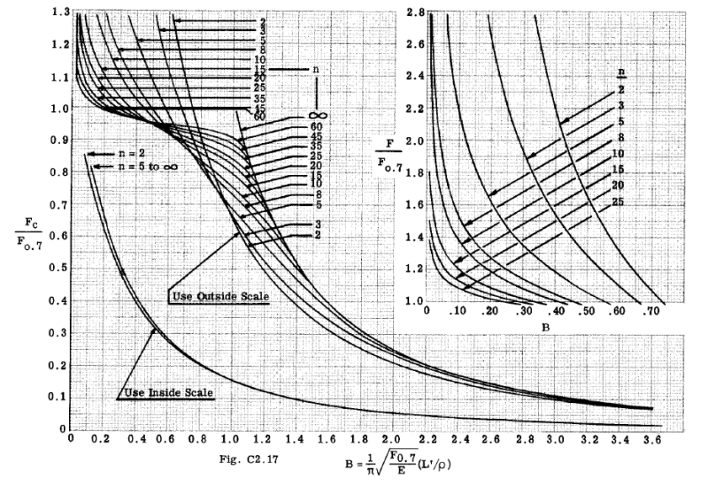
Also, with respect to Fig C2.17 Bruhn, there are two sets of curves (Inside Scale & Outside Scale...what do these represent and in which situations does one inside vs outside curve?)
Untitled1_st8ezk.png


Also if I want to calc crit stress (Fc) using the above curve, I am getting a completely different value.

Totally confused!
 
Replies continue below

Recommended for you

your common sense is good !

do you have McCombs Supplement ? he has "corrected" Bruhn's by including the "inside" scale (!) which is just an extension of the curve , off to the right ... Y values are 1/10th of the outside (so inside 0.09 is at outside 0.9), X values are nonlinear (?) ...
inside 4 = outside 0.2, inside 8 = outside 1, inside 12 = outside 1.8, inside 16 = outside 2.6) but it doesn't matter for your problem (you're in the insert, yes? ... no!?)

from fig C2.17 ... B = 0.96, Fc/F.7 = 0.78 = 30.4ksi
but ... Fc = pi^2*E/(L/rho)^2 = pi^2*10700/50^2 = 42.4ksi ??

remember this is for stable sections.

another day in paradise, or is paradise one day closer ?
 
Hi RB1957,
I do not have the supplement edition to Bruhn (never knew one was published). Let me try to look it up.

The Cross-Section of my column is circular rod. Hence I believe it is stable and Et is applicable.

Any ideas, why my hand calc is giving me a value of crit buckling stress 10 times lower.
 
I haven't used Et, have you worked through Bruhn's example ? I'd've thought it was an incremental approach.

I thought it was odd that Fig C2.17 would say Fc < F.7, but then I guess it's an "n" thing; that the stress/strain curve has slipped off E at a stress much lower than F.7. maybe plot the ramberg/osgood equation ?

As I understand it (which could easily be wrong) Et and stress go together, and your results are sort of confirming that. You calc'd Et from the linear stress, and then calc'd stress again, and got a much lower stress. I think you need to lower the stress used in Et calc, until the recalc'd stress is the same as the one used to calc Et (which might be 30.4 ksi).

Something I'm going to have to think about is how this impacts crippling allowables. If 2024T3 truly goes "inelastic" at a stress much lower than Fcy, then this is the cut-off for crippling (maybe that's why they say cut-off at 80% Fcy ?).

another day in paradise, or is paradise one day closer ?
 
 http://files.engineering.com/getfile.aspx?folder=0f892b27-8a5f-48cd-9504-1f026aaefc44&file=Bruhn_Supplement_(McCombs).pdf
RB1957 said:
As I understand it (which could easily be wrong) Et and stress go together, and your results are sort of confirming that. You calc'd Et from the linear stress, and then calc'd stress again, and got a much lower stress. I think you need to lower the stress used in Et calc, until the recalc'd stress is the same as the one used to calc Et (which might be 30.4 ksi).

You Sir, may be on to something. Some one recently suggested the same except that I have no clue on how to perform the underlined procedure (in fact I don't even understand it at all). If you have some spare time, would you care to explain with an example?

So Bruhn in some of the worked examples, never uses Et. He directly refers to Fig C2.17, calculates the term 'B' and chooses 'outside scale' (never explains why such scale was chosen) and finds Fc by multiplying the value on the vertical scale with F0.7. Easy peasy right?

Thanks for including a link for Bruhn's supplement. Will go through it later.

ESPComposites, my understanding is that, Johnson-Euler soln is only valid for columns with cross-section which are susceptible for crippling i.e. open cross sections (Z, L, I, perhaps even hollow circular). For a solid bar, Euler-Engersser solution is used beyond elastic domain.
 
"ESPComposites, my understanding is that, Johnson-Euler soln is only valid for columns with cross-section which are susceptible for crippling i.e. open cross sections (Z, L, I, perhaps even hollow circular). For a solid bar, Euler-Engersser solution is used beyond elastic domain."

Not quite. The Euler-Engesser solution is only valid for stable cross sections. The Johnson-Euler solution can be used for both stable and unstable cross sections. Technically speaking, the Euler-Engesser solution is more accurate for a section that is stable (because the Johnson-Euler is an empirical curve fit approach), so some people go that route. But the Johnson-Euler is usually considered to be acceptable and should give very similar results. There is no good reason to accept the J-E solution for an unstable section but to reject it for a stable section (though some companies may have strict procedures regarding this distinction).

Either way, this minor difference should not affect your comparison to FEA, which seems to you be your end goal. Also, you will most likely find that the more influential part of your nonlinear FEA (by far) is the choice of how you define the initial imperfection and its magnitude. There is no "real" way to do this, though there are some general rules of thumb.

Brian
 
re the underlined text ...

you've calc'd Fc elastic, when you use that stress to calc Et and re-calc Fc (using Et) you get a really small critical stress.

so that says the stress used to calc Et is too high, try 40ksi, Et will be higher, but Fc(using Et) will still be low. try 36ksi, try 30.4ksi ... (if fig C2.17 is to believed this should work out, ie the stress used to calc Et is the smae critical stress (Fc calc'd with Et).

put another way Et is a function of stress so you've got ...
stress = pi^2*Et(stress)/(L/rho)^2 or
Et(stress)/stress = (L/rho)^2/pi^2

yes?

another day in paradise, or is paradise one day closer ?
 
So RB1957,
Essentially, it is kind of a trail & error procedure. I did a quick Excel calc and it seems to match with Fig C2.17. Phew...

Thanks a lot for explaining it to me.

ESPComposites, thanks for brief explanation. I usually calculate Fcc i.e. Crippling Stress using Needham Method which requires ratio of b/t. How is the ratio of b/t calculated for a circular bar? I believe JE formulation uses Fcc if I am not wrong.

Edit: I assumed Fcc = Fcy = 40ksi and calculated the Fc as per JE expression. To my surprise, the value of Fc came out to be 30540 psi, which is what Bruhn Fig C2.17 provides as well. Awesome!

But you are right. Verification with FE results is my current end goal. And I am having trouble with that. I will create a separate post on Nastran forum.
 
that is awesome ! the planets are aligning ...

another day in paradise, or is paradise one day closer ?
 
I tend to prefer to the J-E solution because it is simpler, less confusing, and easier to check. As you found, the answer is basically the same (which actually should NOT be surprising at all). The J-E solution was empirically established from stable sections and then later extrapolated to unstable sections (i.e. use with Fcc) since there is no way to do that with the Euler-Engesser solution. But I can see how that may be lost in translation.

Yeah, syncing the solution to the FEM will be the bigger challenge because of the "guess" required for the initial imperfection.


Brian
 
Status
Not open for further replies.

Part and Inventory Search

Sponsor