Continue to Site

Eng-Tips is the largest engineering community on the Internet

Intelligent Work Forums for Engineering Professionals

  • Congratulations SDETERS on being selected by the Eng-Tips community for having the most helpful posts in the forums last week. Way to Go!

Inertia - Synchronous Generators Vs Renewables 1

Status
Not open for further replies.

NickParker

Electrical
Sep 1, 2017
441
I read that since renewable energy offers low inertia, it leads to Instability in the Power system, Where as the synchronous generators offers high inertia, it doesn't lead to Instability. I understand that since synchronous generators are rotating masses, they offer inertia and the renewable energies do not have any rotating equipment, they do not offer inertias. What I don't pick up is how it leads to instability

Any Inputs are highly appreciated!
 
Replies continue below

Recommended for you

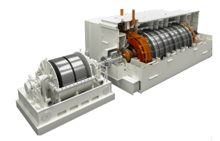
Siemens is now offering large Synchronous Condenser with flywheels, optimized to add inertia. This is one of the suggested solutions in the paper cited by Palletjack


Siemens Energy’s grid stabilizer technology to help Irish grid exceed renewables penetration limit


The utility of the flywheel approach depends on the relative values of inertia, and power factor correction.

Synthetic inertia is a thing, and has proven applicable to some utility battery inverters, but it is somewhat experimental, with only a few installations so far.
Australia leans in on synthetic inertia for grid stability

Expect both to grow.
 
Synchromnous_Generator_hm1sj4.jpg


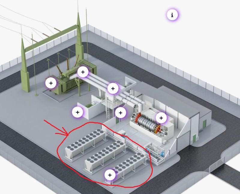
I'm not understanding why these idling synchronous motors (condensers) need a 1/3 of the infrastructure to be cooling.

Keith Cress
kcress -
 
In the diagram there seems to be 3 times as many fans on the motor as the transformer. Perhaps that could correlate to a transformer efficiency of 99% and a motor efficiency of 97%?

For one particular generator I am familiar with, the losses in sync condenser mode are about 3% of the generator nameplate. This is significantly more than the losses in corresponding GSU. I would expect a dedicated sync condenser running in partial vacuum to be more efficient than this particular generator.


I assume Siemens in not yet using superconducting materials.
 
Probably running in hydrogen rather than a vacuum. Hard to extract heat in a vacuum.

I’ll see your silver lining and raise you two black clouds. - Protection Operations
 
The little blue units in the bottom right corner of the plant look like hydrogen compressors.
 
Good points all. Their ad blather stated "for energy saving the rotor runs in a partial vacuum", so maybe not H2. Perhaps the blue things are some form of plumbed-in water cooling, possibly the stator or even insane rotor plumbing?

Still seems like a lot of cooling to me.

Keith Cress
kcress -
 
I think that the flywheel will run in a vacuum, but not the motor. At high ratings (100 MVA +) this could be hydrogen cooled.

Quite a few of the gas turbine driven generators I used to work on had clutches between the generator and turbine, (google ‘SSS Clutch’) so that when the turbine stopped the generator could run on, providing inertia and VAr control etc.

Siemens have taken this a stage further and added further Inertia by way of a flywheel.
As regards cooling of the motor, then remember that friction and windage can be estimated at 1% of the motor rating. If the motor is rated at 100 MVA, then even that is 1 MW!

One of our customers burnt out a 100 MVA generator by running it overnight without generator cooling during turbine commissioning… Obviously the manufacturers fault!
 
NickParker:
"Renewables", at least in the context you are applying it, can include rotating masses (think wind generators, tidal power, and hydroelectric units). They can also have no rotating assets (think solar). Are traditional synchronous machines connected to non-renewable energy sources more massive in terms of inertia? Certainly - because they tend to operate at slower speeds (with the possible exception of hydro and tidal power). Add to that the fact that wind generators tend to be individually lower ratings (although there may be significantly more of them in total).

Does the inertia of the generating unit contribute to system stability? Yes, in terms of ride through capability for short-time disturbances. More importantly, they provide a fairly large source of reactive power - which is what the bulk of today's electrical loads (power electronics, lighting ballasts, and asynchronous machines) require. Without the ability to produce that reactive power (both solar and wind use power electronics on their output to achieve "line frequency", so there's no reactive generation capability), the grid can become unstable with loads "fighting" for the little bit of reactive power out there.

Enter the synchronous condenser - a synchronous machine operating with relatively light "active" power and huge "reactive" power loading. This is not new technology by any means - it's been around since at least the early 1900s. Utilities have been quietly employing it (instead of building new power plants) since the 1950s, at least. For these types of "utility size" units, the ratings are so high that even a small inefficiency adds up to megawatts. Couple that with the fact that a significant portion of the energy is consumed in the rotor (compared to the stator in more traditional units) and it becomes much harder to effectively cool the unit. Hence the need for large-scale external cooling facilities like the artist's conception shown in the manufacturers' brochure.

And yes - the flywheel can operate in a vacuum (sometimes it does, sometimes not, depending on who designed the drive train). The generator itself will likely have H2 or - worst case - He as the gaseous medium to transfer heat from the internal components to where the external system can do something with it.
 
Gr8blu said:
Without the ability to produce that reactive power (both solar and wind use power electronics on their output to achieve "line frequency", so there's no reactive generation capability), the grid can become unstable with loads "fighting" for the little bit of reactive power out there.

Solar and wind converters can generate reactive power, and either source or sink it. One of the common functions of modern smart inverters is volt-var control. The inverter output stage voltage amplitude can be changed with respect to the grid voltage amplitude on the other side of an output inductive reactance (i.e., filter or transformer) to allow reactive power generation to be non-zero. For those inverters using space-vector modulation, the real and reactive power outputs are varied independently provided the apparent power limits aren't exceeded. This means that although a PV array only produces real power, its inverter can turn that real power into reactive power.

Fast frequency response (a.k.a. synthetic or hidden or virtual inertia) is also possible from certain types of inverter-based sources. It can use rate of change of frequency (ROCOF) or ROCOF plus frequency deviation as inputs to control loops to modulate the output real power injected into the grid, and it can do it much faster than rotating machines. This can aid stability.

xnuke
"Live and act within the limit of your knowledge and keep expanding it to the limit of your life." Ayn Rand, Atlas Shrugged.
Please see FAQ731-376 for tips on how to make the best use of Eng-Tips.
 
xnuke: The inverter is typically very limited in terms of the amount of reactive power capability - I have yet to see one that even approaches the 0.80 PF range of a traditional generator, let alone the 0.15 PF range of a modern synchronous condenser.

As a side point: most wind turbine operators set their control scheme up to hold a relatively narrow (+/- 0.98) power factor, in order to optimize their real power output ... which is what they get paid for. No incentive to produce reactive power means no reactive power produced.

Converting energy to motion for more than half a century
 
Water-/hydrogen-cooled generators are fairly common.
Water cools the stator. Hydrogen circulates inside the housing and cools the rotor, and everything else that is not water cooled.

I suspect that vacuum is a poor choice for reducing the generator windage for electrical reasons. The conductivity of most gasses drops as pressure is reduced (think florescent light), and then increases as hard vacuum is approached (think vacuum interrupter). A hard vacuum is very difficult to maintain especially with a large rotating shaft seal, that must be present at both ends of the machine to protect the shaft bearings from the vacuum.

The attachment is an ABB paper on a line of alternators with direct water cooling of rotor and stator, which claim to circulate air inside the housing. The cooling method is claimed to allow shorter rotors, which is another approach to reducing windage.


 https://files.engineering.com/getfile.aspx?folder=c486a86b-7d96-4a42-84d2-cf25e40bae7a&file=10-16_ENG_9801.pdf
Continuation
ABB seems to take a different approach with synchronous condensers, with the units being individually smaller, but using several. Many use an air to water to air indirect cooling approach, or an air to air approach. External flywheels are an option.

Screenshot_from_2021-08-19_20-02-05_ijis42.png


See the attachment. Lots of tradeoffs here to chose from.
 
Flywheels spinning in a vacuum may be more common with rotary Uninterruptible Power Supplies. The flywheels are very large and spin very fast so as to store energy. During an outage the higher frequency output current is electronically converted to 60 Hz.


--------------------
Ohm's law
Not just a good idea;
It's the LAW!
 
One (or more) brand of rotary UPS uses disc drive type technology and “writes” the rotor poles on the fly to maintain a (nearly) fix output frequency over a wide range of rotor speeds. Or, at least they did 15+ years ago.

I’ll see your silver lining and raise you two black clouds. - Protection Operations
 
[URL unfurl="true" said:
https://www.siemens-energy.com/global/en/offerings/power-transmission/portfolio/flexible-ac-transmission-systems/synchronous-condenser.html[/URL]]To provide maximum inertia, Siemens Energy has extended the established synchronous condensers solution with additional rotating mass from a flywheel... Siemens Energy’s flywheels are operated in partial vacuum to minimize air friction losses and reduce the cooling efforts to maintain required temperature level in all operational and emergency modes.

Would it be easier to enclose the entire spinning portion in a partial vacuum rather than having rotating seals?
 
No, because you still need to extract rotor heat across the air gap. Can’t do that well in a partial vacuum.

I’ll see your silver lining and raise you two black clouds. - Protection Operations
 
I suspect all the extra cooling is to greatly exceed the temporary normal limitations that can be seen on the generator curves. It might have been much cheaper to chill the generator rather than build a huge unit. If a neighboring unit trips, this unit will immediately start dumping large amounts of MW and VAR into the system until other units ramp up.
 
Bacon4life,

You could have a magnetic coupling and avoid seals. There are manufactures of magnetic gear boxes for wind turbines.
 
Status
Not open for further replies.

Part and Inventory Search

Sponsor