Eng-Tips is the largest engineering community on the Internet

Intelligent Work Forums for Engineering Professionals

Initial fault current versus x/r ratio in ac system 1

Status
Not open for further replies.

kirkhuyser

Electrical
Feb 26, 2008
3
0
0
US
I engaged ChatGPT to explain how x/r ratio affects fault current. In its initial reply, ChatGPT stated that a lower x/r ratio results in a higher initial current, which I knew wasn't true. I found online test curves comparing initial current for two case, x/r=5 and x/r=50, the latter resulting in the higher initial current. So I told ChatGPT I disagreed. It then reversed itself, telling me what I wanted to hear. But then I questioned why if reactance resists the rate of change of current (due to the magnetic field produced, which I didn't share with ChatGPT), would the initial current be higher for higher x/r ratios. So ChatGPT reversed itself again, apologizing for its mistake.

Bottom line is, I could keep going in circles with ChatGPT, but I'm not going to get the correct answer. It seems contradictory to me that higher x/r ratios result in higher initial fault current. Somehow I suspect it has to do with the build up of the magnetic field, but can someone explain this? Don't hold back on getting very technical, or scientific, if you will. I can handle it.
 
Replies continue below

Recommended for you

In fact higher the X/R ratio meaning the fault current is more inductive
so that initial peak gets higher. Simple example is near a syn. generator.
 
It looks like ChatGPT can carry a conversation, but without any understanding.
Lawyer Uses ChatGPT In Federal Court And It Goes Horribly Wrong
This is the same problem engineers face when using CAE tools beyond there personal realm of expertise. You need to know enough about the tools output to understand when the output is not good engineering practice.
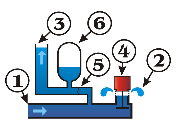
An analog of the OP's question is the hydraulic ram.
Hydraulic_Ram_fzvxco.gif

Making pipe 1 longer increases the amount of energy that can be stored at a particular velocity. When the flow is suddenly stopped by closing 4, the amount of energy in the flowing water translates to a higher pressure at 3.
 
You are both telling me things I already knew. I'm looking for an explanation of why higher x/r ratio leads to higher initial fault current (1st quarter cycle) given that inductance resists rate of change of the current.
 
It has to do with residual magnetism and point on wave of energization.
What are we comparing to?
If we are comparing to a given impedance, then comparing equal impedance circuits, Then the circuit with the higher X/R ratio will has a lower resistive component.

Circuit #1; 5 Oms resistance & 10 Ohms inductive reactance. Impedance = 11.2 Ohms, X/R = 2
Circuit #2; 2.5 Ohms resistance & 10.9 Ohms inductive reactance. Impedance = 11.2 Ohms, X/R ratio 4.36
In the worst case, the combination of residual magnetism and point on wave switching acts to cancel some or all of the inductive reactance and the current may approach a limit determined by the resistive component.
With 100 Volts applied;
Circuit 1# Pure resistance = 5 Ohms, Current will approach 20 Amps.
Curcuit #2 Pure resistance = 2.5 Ohms, Current will approach 40 Amps.
(I am not a Robot)

--------------------
Ohm's law
Not just a good idea;
It's the LAW!
 
An inductor limits current as self induction generates a back EMF opposing the rising current.
With residual magnetism present and zero point switching of the half cycle that acts to decrease the residual magnetism, self induction does not start until both the residual magnetism and hysteresis have been overcome.
The current may approach a value limited by the pure resistance of the circuit.
And a side note:
Waiting for ChatGPT to pass Chaptcha tests.

--------------------
Ohm's law
Not just a good idea;
It's the LAW!
 
Self induction is governed by Faraday's law of electromagnetic induction and is independent of residual magnetism or hysteresis.
 
Sorry, getting old.
Wrong direction of residual.
The effect that I was looking for was saturation.
Once an electromagnet is saturated, there is little change in flux strength to drive self induction.
The coil now acts as an air core for further increases in magneto-motive force.
As an alternating potential increases from zero to maximum, the flux increases from zero to the design limit.
If the potential is applied at the zero crossing and there is already some residual magnetism, the increase in flux density may reach saturation before the potential sign wave peaks.
There is still self induction but it is reduced by a ratio related to the permeability of the core.
When the alternating magnetomotive force drives the core into saturation, the impedance for further increases in current
acts as an air core reactor rather than an iron core reactor.

--------------------
Ohm's law
Not just a good idea;
It's the LAW!
 
Without doing any math - in real life, in real circuits, the general rule is the higher the fault current the higher the X/R and likewise the higher the X/R the higher the fault current. Neither is dependent on the other, but both are indicative of the stiffness of the system. (Staying away from areas influenced by the presence of series caps.)

If you had an ideal source and put a zero impedance fault on its terminals I don’t think the X/R of the source will affect the fault current. Once you have some impedance between the source and the fault, each with its own X/R, varying each with the other held constant will result in differing fault currents.

I’ll see your silver lining and raise you two black clouds. - Protection Operations
 
It's not just the initial fault current. If you solve the differential equation, there will be two components of current - the steady state (ac symmetrical) and a transient component. The transient component is a function of the phase angle of the voltage at the start of the fault and the X/R ratio. The transient component is a decaying dc offset current with a time constant equal to the X/R ratio. For high X/R values, this dc offset current can last for many cycles. If the fault occurs at zero volts, this creates the maximum dc offset current. If the fault occurs at maximum voltage (assuming a nearly purely inductive system), there is very little dc offset current. A key thing to remember is that the current must lag the voltage by 90 deg (or close to it for a typical system).

But you are correct that the maximum fault current always occurs in the first 1/2 cycle.

 
 https://files.engineering.com/getfile.aspx?folder=1fa9494e-f8a9-4ce3-85d0-61a47d00f8d3&file=Picture1.png
That's my understanding too, dpc.
Higher X/R delays the decay of the fault current and as a result, the current seen by the circuit breaker which needs to interrupt the current sees a higher magnitude of current and a higher DC component. This is what is challenging for the Circuit breaker.
Also, this poses a challenge for the current transformers as higher DC component tends to saturate the CT core.
 
Continuing from DPC's post: The X/R affects not only the duration of the DC component but also the asymmetrical peak value of fault current. Consider a case where the short circuit occurs at a voltage zero point when the fault current will be a maximum. If the X/R of the transformer is 2, then the short circuit current through the transformer will increase by 1.27 times compared to the peak value of the sinusoidal symmetrical short circuit current. With X/R =10, this will be 1.77 times and 1.98 times for an X/R = 100. Transformer manufacturers design the windings to withstand forces from this enhanced peak of fault current. Transformer standards (IEC &IEEE) specify such a requirement.
 
When the fault first initiated, the current through the source inductance cannot change instantly, so it the physical current is stuck at zero. For modeling purposes, we often split the physical current into two modeling components that start off with equal magnitude and opposite polarity. The AC component increases at sinusoidal and the DC component decreases at an exponential rate. For small values of X/R, most of the DC component decays away before the first AC peak occurs. For large values of X/R, most of the DC component is still present by the time the first AC peak occurs.

Taking it to the extreme, imagine an AC source in a series circuit with a pure inductor and switch. The AC current would oscillate between 2*V/X and 0. Adding any amount of resistance would allow current to slowly progress to oscillating between +V/X and -V/X.

Some parts of our industry use X/R and other use R/X. I can see why ChatGPT might get confused.


A few more thoughts:
As you know traditional sources on an electrical system consist of either generators or transformers, both of which tend to be highly inductive - large power transformers tend to have X/R ratios of 10 or so, and large generators can have X/R ratios of close to 100. Lines and cables generally have much lower ratios. The highest fault currents are generally close to the sources, and thus high fault currents generally have high X/R ratios in power systems.
As a point of interest, generators have high X/R ratios which, as was stated above, means long time constants for the DC component of the current to decay. Generators also have a decaying AC component due to the time varying fluxes in various magnetic circuits in the machine. This gives rise to a scenario in some generators where the AC can decay faster than the DC in the beginning of the fault - the total fault current can possibly fail to cross zero for several cycles (a “delayed current zero”). Large generators have a specific IEEE standard for generator breakers (IEEE C37.013) which among other things addresses this phenomena.

 
Status
Not open for further replies.
Back
Top