Continue to Site

Eng-Tips is the largest engineering community on the Internet

Intelligent Work Forums for Engineering Professionals

  • Congratulations waross on being selected by the Eng-Tips community for having the most helpful posts in the forums last week. Way to Go!

Inlet/Outlet location on Rectangular water tank

Status
Not open for further replies.

jkate

Mechanical
Nov 5, 2011
66
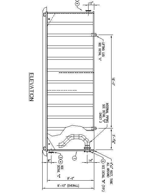
I have a rectangular water tank with weir plates inside. Water flows into the tank at "X" gpm through an inlet nozzle. Water flows under the first weir then over the top of the second weir and then exits the tank through and outlet nozzle. I would like to maintain the level in the tank at 12" down from the top edge of the tank. The inlet and outlet connections are both located toward the top of the tank. I'm trying to determine the proper location (height) of the inlet and outlet connections so that when flow stops, water doesn't back siphon out through the inlet connection. Is there a formula that will calculate how high the water will rise inside the effluent nozzle as it starts to flow out of the tank? I'm thinking wherever that water level is, will be the operating level of the tank. To prevent the back siphoning, the inlet nozzle should be a few inches above that water level. Can someone give me a little guidance with this? Much appreciated.
 
Replies continue below

Recommended for you

Draw your tank in elevation view, approximately to scale with the centerline, top and bottom of the two proposed nozzles indicated. I think there will be a nasty air trap in between the two.
 
Mixing_Tank_awgkyb.jpg
 
Estimating the flow in a partially full pipe is a little more difficult. Here is an online spreadsheet:


Estimating flow over a weir is simpler. Estimate the flow over a weir with one of the online calculators or tables. Here is an example:


I would not recommend a pipe on the outlet. What happens with a pipe outlet is that you will get air trapped and the fluid flow will transition between full flow and partial full flow. With trapped air, it will block the flow, so you will get fluid surges until the air is pushed out. With a horizontal outlet, it is also difficult to maintain the elevation.

If you want to control the elevation of water, you will need to put a wier or pipe elbow to the water surface on the outlet. You may oversize the outlet, so you do not have to worry about full or partially full.

You need a vent on the inlet pipe or shortened leg, otherwise, the inlet pipe will back siphon out of the tank.

Rotated the tank for you:

tank3_q6ebu9.jpg
 
We really need to see what happens to the inlet pipe away from the connection.

If it goes up, but the inlet nozzle is not fully submerged, you won't get a syphon effect on cessation of flow, more that the inlet pipe will drain out.

Much depends on this orientation and velocity of flow in the inlet pipe.

Anything less than 1-2m/sec and it probably means your pipe isn't full.

what is this? - some form of API separator? If you have no other outelts I don't see what the second weir is doing for you?, noting that's it's not really a weir, just a baffle plate as the liquid level is much higher than the weir

Is the tank atmospheric? - where are the air vents

Ditto as bimr says for your outlet pipe. You could either end up with a syphon or an air lock / bubble if there is something connected to this outlet.

Why the internal pipe? you seem to be complicating things by having that strange internal pipe.

Remember - More details = better answers
Also: If you get a response it's polite to respond to it.
 
The tank is atmospheric (open top) and used as a Coagulation/Flocculation tank in the water treatment process. True, what I called weirs I suppose are really baffles. Moving from left to right, Coagulant is added into the first chamber where there is a high speed mixer to disperse the chemical. Water continues past the second chamber and over the final baffle where the flocculant chemical is added and a slow mixer allows the floc to get larger. Water floc exit the tank and goes to a clarifier.
 
So do any of the responses help? You've answered some questions but not all.

Remember - More details = better answers
Also: If you get a response it's polite to respond to it.
 
I have seen these in water treatment plant. All tanks are atmospheric, flows are minimal, pipe lines are often not full flow. It is series of tanks overflowing from one to the next. Shouldn't be difficult to design.

Regards,
Curtis
 
Standard practice would be to enable a syphon break at 11ft or so below the top of the tank. This can be a simple as a 1/2inch weep hole on the top of the inlet line.
 
Thank you all for your replies. Was really looking to see if there was a calculation that would determine how high the liquid level in the tank would rise at a known flowrate and a know exit pipe size.
 
Yes there will be, but what is on the other side of the exit? - Nothing, i.e. it is like an open nozzle or do you have pipes taking the piqued somewhere else?

Getting a pressure drop along that flexible pipe on the inside might not be easy either

Remember - More details = better answers
Also: If you get a response it's polite to respond to it.
 
There is horizontal piping that feeds the water to a clarifier which is also atmospheric.
 
It will take you 10 minutes with the calculator listed above. If you don't have that, post the flow conditions and somebody will calculate it for you.
 
You should just put a little hole in the pipe at the
nozzle on the inside of the tank to break the vacuum?
 
Truly horizontal?

What size?

How long?

So yes there are ways of working out what you want to know, but you need to establish all the required elements and then work it out.

One simple equation - not in this instance.

What flow rate are we looking at here? / velocity through your exit pipe? It may be that there is a simple way of looking at it if the flows are quite low.


Remember - More details = better answers
Also: If you get a response it's polite to respond to it.
 
Sounds like the whole thing is gravity driven. In which case the outlet invert will need to be lower than the inlet invert. Otherwise, when the influent ceases to flow, it will stop within the inlet pipe itself.

I usually deal with grease/oil/dirt interceptors, not what you are trying to separate, and the outlets are typically 1-2 pipe sizes below the inlet. This allows the inlet pipe to empty when there is not flow.
 
Status
Not open for further replies.

Part and Inventory Search

Sponsor