In the context of VFD applications, these terms are unfortunately often misused by marketing types or are mistranslated when documentation is initiated in another language. So what waross and bacon4life have said is true, but may end up somewhat "muddled" in the real world.
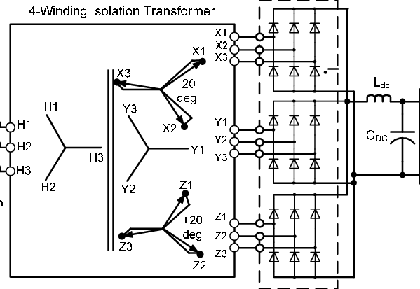
If you are needing harmonic mitigation with VFDs, ONE of the ways that can be done is to use a multi-phase transformer into a multi-pulse rectifier, for example 12 or 18 pulses. "Pulses" refers to the number of diodes, so for an 18 pulse drive arrangement, you have 18 diodes, 2 per phase, so the drive is fed with 9 phases from 3 sets of 3 phase windings, each one phase shifter from the next by 20 degrees. That is all done magnetically inside of the transformer, so is often called a "phase shifting transformer".
In the image above, this is depicted as an "isolation transformer" as well, represented by the two parallel lines in the middle. That does not necessarily need to be the case, in fact a lot of 18 pulse transformers used in VFD packages are less expensive "autotransformers", meaning the primary and secondary windings are not separated. The point being that these two concepts are NOT the same, but CAN BE made in the same unit.
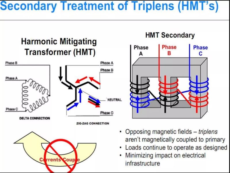
Some people will refer to these as "harmonic mitigating transformers" because that is how they are USED, but there are actual "Harmonic Mitigating Transformers", or HMTs, that work differently. These are special designs called "zig-zag" transformers (or similar) that neutralize harmonics in the way they are wound and are an ALTERNATIVE to multi-phase transformers in that they don't require a special VFD front-end rectifier design. HMTs are used for more than just VFDs, they can neutralize harmonics from any source (within their capacity). And again, they CAN be isolation type or not.
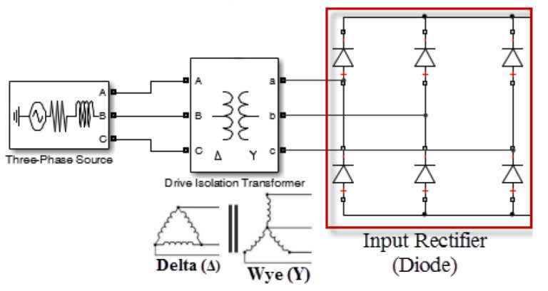
As to "isolation transformers", as mentioned, that just refers to there not being a direct electrical connection from primary to secondary. But in the VFD context, there are special "Drive Isolation Transformers" (DITs) that do not necessarily change the
voltage, they are often used to change the configuration (and provide the isolation). So for example, almost all VFDs are designed to be used on a solidly grounded Wye distribution system, where the line to ground reference voltage is 58% of the line to line voltage. If you were to have a Delta power distribution system, that can be very detrimental to the VFD, causing premature failure. So you can buy a DIT that is, say 480V Delta primary, 480Y277V secondary. The 277V is never used, but the transformer X0 terminal is grounded, so the VFD line side connections sees a 277V maximum to ground, as it was designed. But because the primary of that DIT is Delta, it does not interfere with the reasoning for the entire facility to be using a Delta system.
DITs are sometimes referred to as "converter transformers" for this reason, because MOST converter type equipment (AC VFDs, DC Drives, Servos, UPS etc.) are going to require that solidly grounded source. In addition, DITS (or other isolation transformers) are also often needed when you have "Active Front End" (AFE) VFDs, to avoid LCL filters on them from resonating with other AFE or standard low impedance drives (meaning no Line Reactor or DC bus choke) on the same line source. But technically, although all DITs are "converter transformers", not all converter transformers are used for "drives", so they use that terminology for those other uses.
" We are all here on earth to help others; what on earth the others are here for I don't know." -- W. H. Auden