Hello,
I need to create fastener holes pattern on a curved part (wing skin panel) and I am having issues. First time trying to create a hole pattern on curved surfaces.
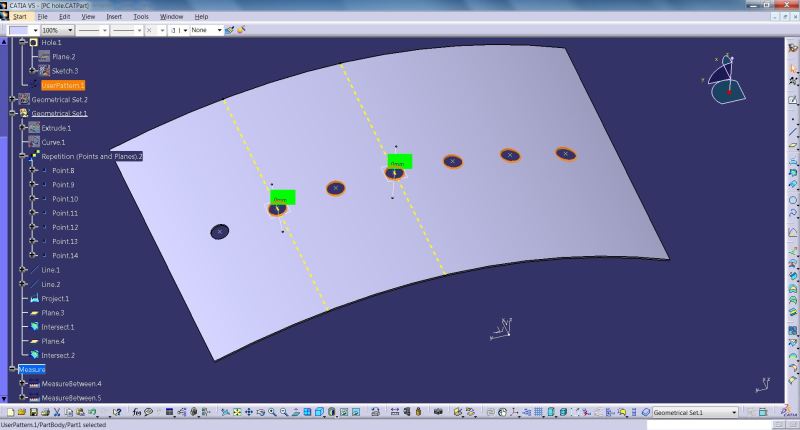
Since there are like hundred of holes, I decided to create a sketch with points and use the function User Pattern to pattern hole feature. In my prior usage, this approach has worked beautifully albeit most of the parts/components were flat surfaces.
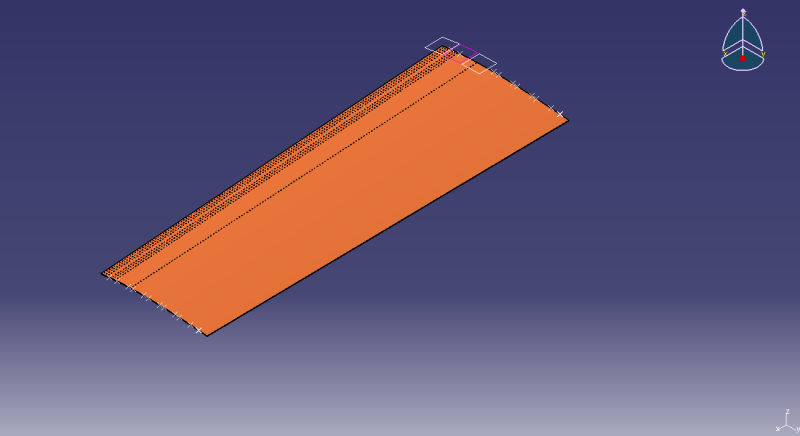
Image below shows the 3 different sketches with points representing fastener hole center location.
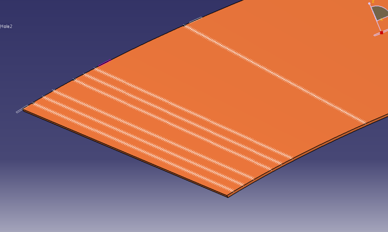
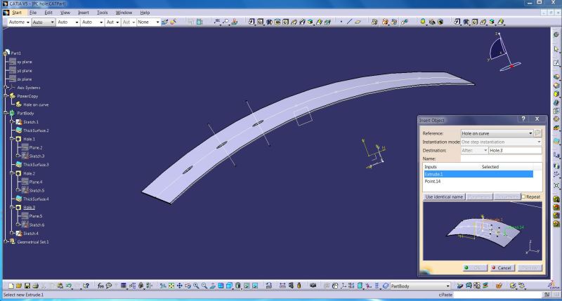
I created the usual hole feature on skin surface as shown below.
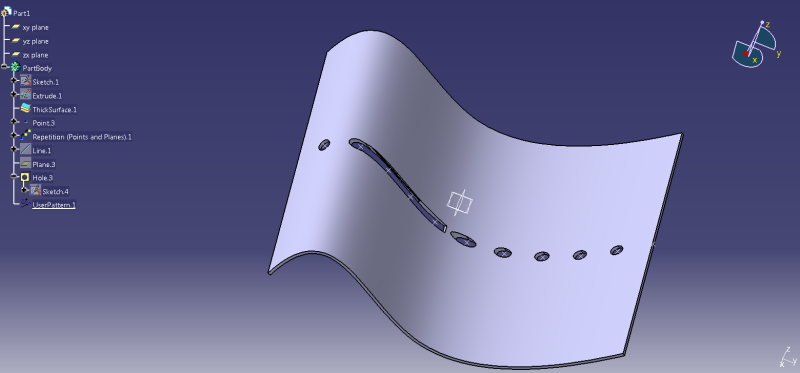
But when I pattern them, things start to go awry.
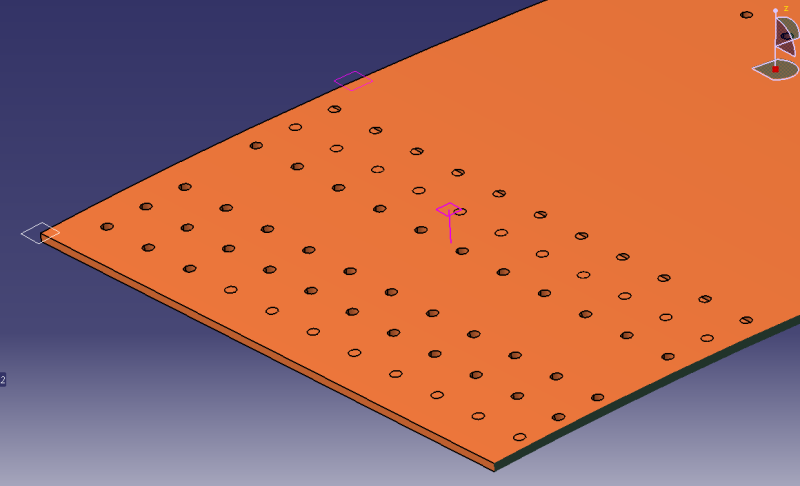
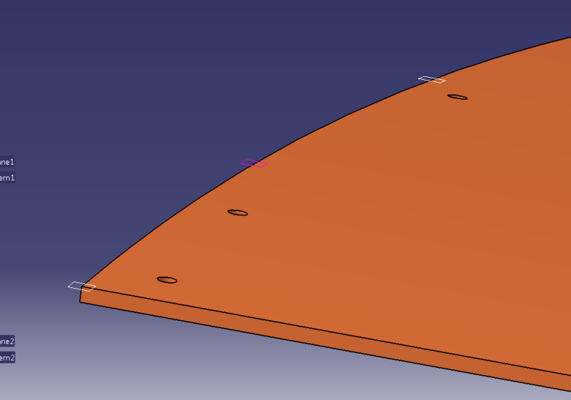
Hopefully, this can be seen but somehow in one of the rows, the hole feature is not being drilled i.e. hole is present but it doesn't appear to have removed any material.
In another pattern, things are even more weird. As illustrated, Catia seems to be have created like half a hole?
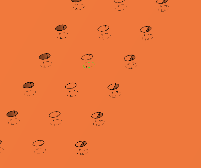
Anyways, I understand in principle of parent hole feature drilling direction which in turn is based on surface normal and this could vary over the span of a curved surface and hence the weird outputs after patterning.
Is there a better way to achieve inserting holes on the skin panel? It is important that hole features are represented in the CAD model.
Would really apprecaite help on the above as it is kinda important that I find a way to accomplish the task.
Thanks in advance.
I need to create fastener holes pattern on a curved part (wing skin panel) and I am having issues. First time trying to create a hole pattern on curved surfaces.
Since there are like hundred of holes, I decided to create a sketch with points and use the function User Pattern to pattern hole feature. In my prior usage, this approach has worked beautifully albeit most of the parts/components were flat surfaces.
Image below shows the 3 different sketches with points representing fastener hole center location.
I created the usual hole feature on skin surface as shown below.
But when I pattern them, things start to go awry.
Hopefully, this can be seen but somehow in one of the rows, the hole feature is not being drilled i.e. hole is present but it doesn't appear to have removed any material.
In another pattern, things are even more weird. As illustrated, Catia seems to be have created like half a hole?
Anyways, I understand in principle of parent hole feature drilling direction which in turn is based on surface normal and this could vary over the span of a curved surface and hence the weird outputs after patterning.
Is there a better way to achieve inserting holes on the skin panel? It is important that hole features are represented in the CAD model.
Would really apprecaite help on the above as it is kinda important that I find a way to accomplish the task.
Thanks in advance.
")