Continue to Site

Eng-Tips is the largest engineering community on the Internet

Intelligent Work Forums for Engineering Professionals

  • Congratulations IDS on being selected by the Eng-Tips community for having the most helpful posts in the forums last week. Way to Go!

Install Groove Around Part Perimeter 1

Status
Not open for further replies.

BrittToolEngineer

Aerospace
Aug 4, 2016
239
Greetings:

I have a part that sets on a buck. The buck is contoured per part data. After the contour is installed, we need a .25 wide groove x .1875 dp around the perimeter of the part. I have attached a parasolid of the actual parts and my attempt to install the groove. With my groove currently installed, I'm unable to put the .125 Radius blend in each corner nicely all the way around. Can anyone help me with this problem. I'm using NX11.

Thanks,

Brent
 
 https://files.engineering.com/getfile.aspx?folder=af3b9b31-ab94-4c32-850a-bc0db47f5319&file=.25_ball_nose_visual_groove2.x_t
Replies continue below

Recommended for you

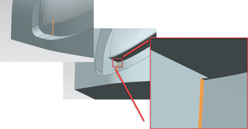
Is this the issue ?
image_ohna2d.png


Regards,
Tomas
 
Tomas,

Yes, I believe that is the issue. Not sure how to make my trim bodies consistent on the bottom where they trim to make smooth surfaces that will enable the blend to go in nicely.
 
How do You created this model? The surfaces are fold up. Try maybe optimalize face? You can also add some small radius on this orange face. There is also option to unsew some surfaces and create new ones by for example swept, and then sew them to old ones.

With best regards
Michael
 
mmauldin, just noticed this post. I've downloaded your help and will look at it tomorrow. Thank you for your time in this.
 
mmauldin, thanks a bunch for helping. What you had was much closer than what I had and you've shown me methods I did not think of. Thanks again.

Brent
 
Status
Not open for further replies.

Part and Inventory Search

Sponsor