Continue to Site

Eng-Tips is the largest engineering community on the Internet

Intelligent Work Forums for Engineering Professionals

  • Congratulations IDS on being selected by the Eng-Tips community for having the most helpful posts in the forums last week. Way to Go!

Intentionally roughened edge of precast panel for shear friction 2

Status
Not open for further replies.

Prestressed Guy

Structural
May 11, 2007
390
I am using shear friction for shear transfer across panel to panel joints in a seismic wall project. To use a value of 1.0 for µ, Table 22.9.2.4 calls for 1/4" amplitude. I have read somewhere in the PCI material that on green concrete, a heavy sandblast will achieve sufficient roughness for µ = 1. I have a 3rd party review which is asking where I found that and now I cannot find it again.

Anyone know of any documents talking about intentional roughening by sandblasting?
 
Replies continue below

Recommended for you

You may want to consider some other method of shear transfer... this sounds like an expensive solution.

Dik
 
A heavy sandblast is a simple thing to do on green concrete. We routinely do it to the entire face of panels for architectural reasons so just the edges is simple.
 
Don't you also have to connect the parts together? Do you have a typical detail?

Dik
 
The connection is with boundary reinforcement that is joined with NMB sleeves or headed rebar into corrugated grout sleeves. The tension bars provide the Avf and the concrete is the faying surface.
 
The accepted/preferred method in this part of the world is to use a retarder (like sika rugasol) and waterblast these areas when the panel is released from the form. Achieves the same surface roughness required by the code. The downside is usually the guys forgetting to use the retarder, or applying it in the wrong location, or using too much/too little.

I don't see it very often, but you can also use a needle gun to roughen the concrete, but unsure how this would work on green concrete. Also seems very labour intensive.
 
The usual method of providing a shear connection between panels is to cast in a keyway. We only use roughened surfaces when pouring new concrete against existing concrete.
 
I've never seen a shear key cast into a panel joint. Hotrod10, can you find a picture of what you mean, is the key(s) perpendicular to the length of the panel to increase interlock, or parallel like you might see in thicker slab on grade construction joint?

I've only seen intentionally roughened surfaces and gap between panels being filled with grout for the horizontal joints (or a dedicated insitu strip with reinforcement lapped out of the ends of panels for the vertical joints). In the region of the joint faces top and bottom or sides, this is simply new grout placed on existing concrete. I can understand a shear key might help to increase surface area or interlock, but I'm not aware of any provisions in codes that might require it (interested if there is?).
 
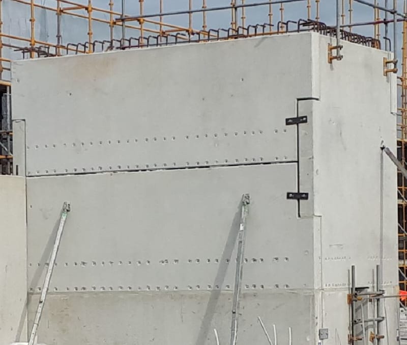
This is the type of "shear key" I see used a lot.

Capture_ewuyrx.jpg
 
Retro... neat... not seen that before, but, placed the idea in my toolkit.

Dik
 
Forgot to mention that the steel plates across the joints are only there for temporary stability during erection. There is a central vertical dowel that gets grouted across the joint.
 
Something like that would be nice but someone had the bright idea to cover the panels with thin brick!
 
I was thinking you were talking about a joint where at least one side was cast-in-place concrete. For a grouted joint between 2 precast sections, I would consider something similar to the joints typically used between precast decked bulb tee bridge girders.
 
Retrograde, curious as to how that arrangement is designed/analysed.

So I'm assuming there is no horizontal reinforcing crossing between panels, and each 'key' transfers vertical load sort of like a bearing corbel engaging the one above and below with the help of the continuous(?) vertical dowel? I assume the dowel is feed and grouted through several panels once they are all in place? (or does the dowel simply developed either side of the joint?)

How is it modeled if it can transfer vertical loads but not so great at the horizontal face loads being transferred to the return wall.

Never seen it before either, but I can see it would work, the only concern is that the panels are wholly reliant on the vertical bar (and whatever reinforcement is encapsulating these at top and bottom of the key) to hold the corner together.

Don't suppose you have a drawing detail you can cut and paste showing how its been reinforced?

Haydenwse... sorry for the hijack.
 
If you want a strong joint, consider how concrete overlays can be bonded on old concrete. Old concrete is cleaned of dirt, etc. and is roughened, followed by vacuum removal, left bone dry. Immediately before placing new concrete, a Portland cement & water paste is brushed on and new concrete placed.
 
Generally the walls are analysed as monolithic and the key is checked that it can take the longitudinal stress at the interface. The strength of the key can be supplemented with internal welded corner plates if required.
 
Status
Not open for further replies.

Part and Inventory Search

Sponsor