Hi everyone,
I'm stuck at calculating the design shear resistance for concrete interface cast at different times. From Eurocode 2 Clause 6.2.5(1) Equation 6.25, there is contribution from the 'external normal force across the interface'.
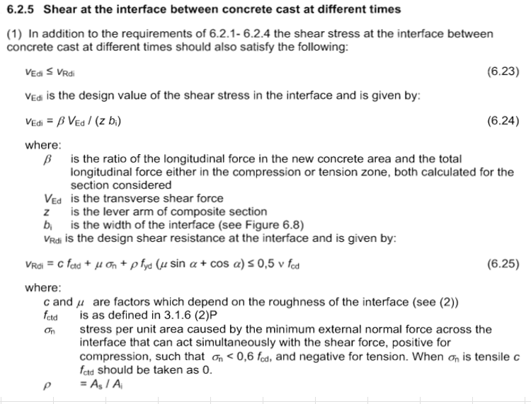
My senior opined that this value is equivalent to the horizontal shear force due to Bending Moment, but I can't seem to find any elaboration from the Eurocode/book on how to calculate it if that's the case. Hope anyone could share where do I get this value. Thanks!
I'm stuck at calculating the design shear resistance for concrete interface cast at different times. From Eurocode 2 Clause 6.2.5(1) Equation 6.25, there is contribution from the 'external normal force across the interface'.
My senior opined that this value is equivalent to the horizontal shear force due to Bending Moment, but I can't seem to find any elaboration from the Eurocode/book on how to calculate it if that's the case. Hope anyone could share where do I get this value. Thanks!