Eng-Tips is the largest engineering community on the Internet

Intelligent Work Forums for Engineering Professionals

Interlocking 4-20mA

Status
Not open for further replies.

TugboatEng

Marine/Ocean
Nov 1, 2015
11,388
0
36
US
I have an application where I need to interlock a 4-20mA control signal but interrupting the signal with a relay caused a nuisance alarm. I need to establish a minimum signal level.

For the details, this is a clutch interlock on the throttle of a diesel engine. The interlock is a relay operated by a pressure switch. The controller outputs 0-10V for the throttle signal, there is a converter to 4-20mA. The interlock is currently on the 0-10V side and is not reliably passing the voltage signal. I proposed moving the relay to the 4-20mA signal. I have confirmed through the manufacturer of the controller that the relay should be installed in the 4-20mA leg. However, it causes a nuisance alarm.

As a solution, I'm thinking of adding another 4-20mA isolator and to install the relay between the two isolators. I need an isolator that will take 0mA in and output 4mA. I purchased a Phoenix Contact MINI MRC-SL-I-I as it lists having both 0-20 and 4-20 in/out but I see now that it is not configurable (out=in). I don't think it's going to work. I may try the MCR-SL-UI-UI-UI.

Any thoughts on this?
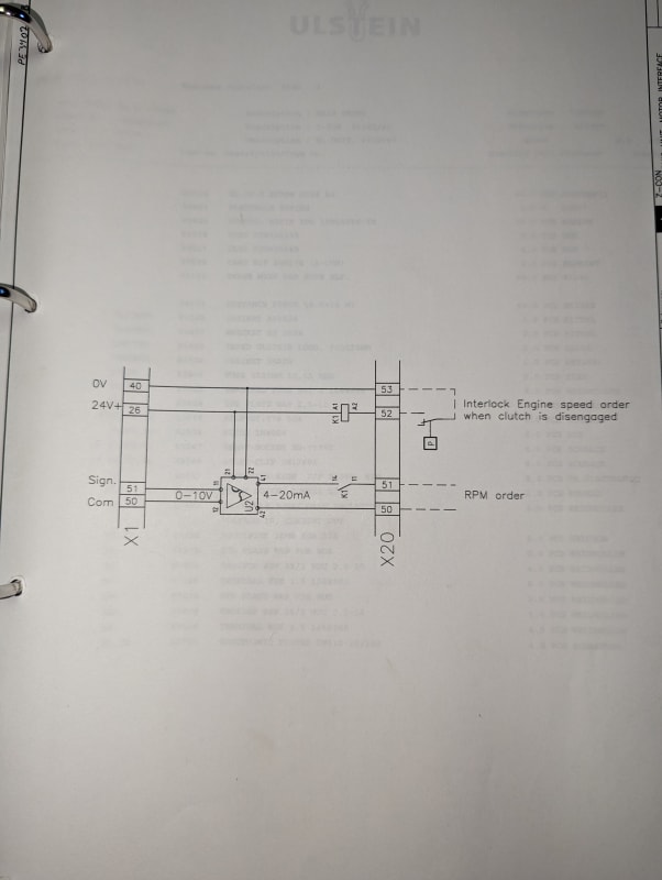
PXL_20230721_180312262_wbf0mb.jpg
 
Replies continue below

Recommended for you

What's the engine speed supposed to do when the clutch disengages? Doesn't the engine have to have a valid 'demand' signal? Isn't an open circuit on the throttle supposed to be an alarm condition?
 
Engine speed defaults to low idle when the clutch disengaged. This is set on the engine control module.

That's exactly the problem. The engine throttle input is 4-20mA so when the relay breaks the signal the engine alarms throttle calibration error. The builders moved the relay to the 0-10V signal as an open doesn't cause an alarm.

Currently the engines are intermittently not responding to the throttle command correctly. They are behaving as if the potentiometer is bad. In my experience potentiometers don't usually give intermittent faults. I have traced the problem back to this relay. I believe that when switching a voltage signal there isn't enough current across the contact to keep it clean.

I received 6 of these engine systems, they're all about 30 years old and they all have similar issues. The previous operators had been replacing the relays periodically but the random occurrences create hazardous conditions.
 
I think I see your problem. You can use a closed contact from the relay to short circuit the 4-20ma signal if the alarm indicates an open loop at the source. I think your alarm happens at the other end. If you want a reliable 4 ma continuous source, then just purchase a thermocouple, RTD or other type input isolator that converts to 4-20ma. As long as the signal is below minimum, it should always output 4 ma.

Brad Waybright

The more you know, the more you know you don't know.
 
The alarm is on the sink. I got the MCR-SL-i-i isolators today. I misread the datasheet and they will not work.

I have ordered the MCR-SL-UI-UI which is configurable by dip switch. My current plan is to take the existing Slimpak G408 and configure it as a 0-10V input and 0-20mA output. The MCR-SL-UI-UI will be configured as 0-20mA input and 4-20mA output. I will place the relay in the 0-20mA segment.
 
Use a sealed gold contact relay for low signal levels like that.

Energize the relay from the control when more rpm is required and use the NO contact to pass the 0-10V speed signal to the converter.

Put a resistor across the 0-10V input if necessary to ensure 0V when the relay is open.
 
Your mention of gold contacts has led me to some new knowledge. I did not know that relays had a "minimum switching current".

Screenshot_20230726-113844_ktu6qg.png


I still plan to move forward with switching the 0-20mA circuit. What are your thoughts of using a solid state relay to switch a mA process signal? I know they create a voltage drop but that shouldn't be an issue with mA signals?
 
Ok, now a can of worms has been opened. I have many pressure switches that seem to develop hysteresis at which point they get replaced. I always attributed this to high vibration exposure. The ones I have dissected always appear to be fine mechanically. The loads for these switches are usually in the 100k+ impedance range. Maybe I'll get longer life from the switches if I short the load to (-) with a 20k ohm-ish resistor depending on the switch's minimum switched current rating.
 
Thanks for the help, job is done. I added a second converter and replaced the relay with one that has gold plated contacts.

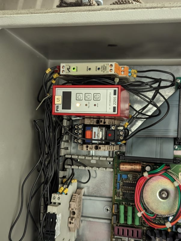
Before:

PXL_20230728_202041104_njnfha.jpg


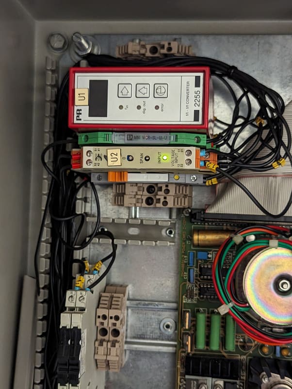
After:

PXL_20230728_202000559_roql6r.jpg
 
Status
Not open for further replies.
Back
Top