Eng-Tips is the largest engineering community on the Internet

Intelligent Work Forums for Engineering Professionals

  • Congratulations waross on being selected by the Tek-Tips community for having the most helpful posts in the forums last week. Way to Go!

Internal Curved Corners in BS 8888 - (Revisited) 1

Status
Not open for further replies.

Munro85

Marine/Ocean
May 5, 2022
5
0
0
GB
Engtips_a4kaqi.png
thread1103-485002

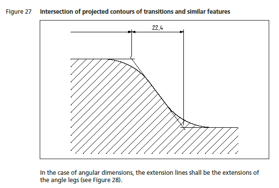
Just following on from the previous thread, I can understand why you would use an Intersect Dimension for a feature such as the upper radius in the figure, as this is where there will be material before the radius has been machined. I don't understand why you would use an intersect for the lower dimension as this material, which the intersecting lines would theoretically remove is used, rather than perhaps showing and dimensioning the Centre mark of that radius.

I just want to clear up that this is a standard way to dimension this "Internal" radius or if it would be clearer using the centre point.

Thanks
 
Replies continue below

Recommended for you

If the radius changes then the center will move; the intersection will not. Suppose that radius had a large variation - say between half what is pictured and double what is pictured. Place the center point for each case. There will be a horizontal distance between them.
 
wow 3 ddave good answer sir. also to stay consistent with dimension is is good practice. how ever i have done both. in this case it is done by the specification. so a process engineer must clarify this on the planning for the floor and inspection. so it is drawn, machined and inspected in the same method.
 
If it is a TED (theoretically exact dimension) none of this matters.
The inspector will not have to measure and report the dimension value.
 
Mr Burunduk some of my customers require these dimension to be inspected and recorded. either with a CMM or with a optical comparator.
during machining it has to be inspected as first article. this has been done before my time.
 
It is true, if there is a direct tolerance applied to the dimension.
The question is in the context of the British standard, which is based on ISO. If it is anything like in ASME, I would not recommend applying a directly toleranced dimension. Considering a form error of the planar surfaces such as convex/concave, the intersection points on an actual part may be ambiguous.
 
yes they can be a pita, and especially in internal diameters. and can be very difficult to inspect. and should be not used unless really necessary. standard shoulder with a corner radius is
so much preferred. and is much easier for every ones sake. easier to machine, inspect and to record.
 
mfgenggear,
It gets worse, when you consider that a dimension like 22.4 shown above and its directly applied tolerance is supposed to apply in 3D. Not just as a 2D projection measurement of some local elements.
 
Status
Not open for further replies.
Back
Top