Continue to Site

Eng-Tips is the largest engineering community on the Internet

Intelligent Work Forums for Engineering Professionals

  • Congratulations SDETERS on being selected by the Eng-Tips community for having the most helpful posts in the forums last week. Way to Go!

Intersect produces disjointed curves

Status
Not open for further replies.

pamakela

Mechanical
Dec 19, 2011
71
Hi,

quite often when I perform an intersect between a (continuous) set of surfaces and a planar surface, the resulting 3D curves are not continuous. There appears to be very small gaps between the curve segments. Is there a way to fix this?

A bug or feature of SW(17)? We need to stick to 2017 for now.
 
Replies continue below

Recommended for you

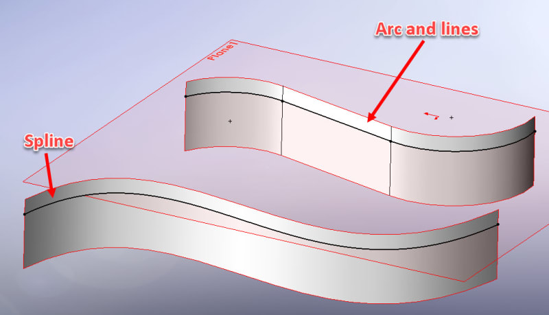
Is it truly continuous? Arcs and lines making a surface is not a continuous surface. Using a Fit spline is a true continuous surface.

See this example:
Arcs_and_lines_ajx9iv.jpg


Scott Baugh, CSWP [pc2]
CAD Systems Manager
Evapar

"If it's not broke, Don't fix it!"
faq731-376
 
Thanks for the replies. This case represents the upper situation shown in SBaugh's reply. But regardless of continuity, shouldn't the resulting intersect curve(s) be connected? Connected is enough for me in this case. But these gaps.. why are there gaps? Very small ones that you can actually see only when you zoom in really close. The surfaces I use - in addition to the planar surface - are from a solid body so definitely no gaps there.
 
It appears there are gaps. But are there actual gaps? Have you measured? Could just be poor graphic resolution.
 
One way to determine if there are gaps is to extrude as a surface then you can measure edge to edge.

I have never seen this sort of bug if it is a bug in SW 2017. It would be helpful if you have an example file this is happening too that you can share with us.

Scott Baugh, CSWP [pc2]
CAD Systems Manager
Evapar

"If it's not broke, Don't fix it!"
faq731-376
 
Status
Not open for further replies.

Part and Inventory Search

Sponsor