Continue to Site

Eng-Tips is the largest engineering community on the Internet

Intelligent Work Forums for Engineering Professionals

  • Congratulations KootK on being selected by the Eng-Tips community for having the most helpful posts in the forums last week. Way to Go!

Intuitive Explanation for Window CT

Status
Not open for further replies.

111R

Electrical
May 4, 2012
114
As current flows through a bus that has a window CT wrapped around it, it's stepped down by the CT ratio. 100 A through a 100:5 ratio window CT results in 5 A secondary.

If 5 A of current is applied through the secondary winding of the CT, does this cause 100 A of current to flow through the bus? If the bus is de-energized and isolated, how is this ratio maintained? Where does the current flow?
 
Replies continue below

Recommended for you

This question may be better answered on Project Board.
image_guwpxm.png


Bill
--------------------
"Why not the best?"
Jimmy Carter
 
I suggest you begin by imagining a 1 to 1 CT and injecting a hundred amps. This CT could be removed without changing much and then you could inject your 100 amps directly into the bus. Where does this current go when the bus is isolated? This will not give you the final answer, but perhaps begin you on the right path.
 
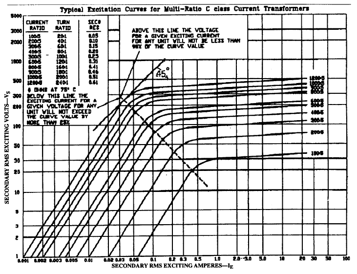
Obviously, if the primary bus is isolated, the primary current will be zero. All of the current injected in the secondary will be magnetizing, or exciting, current. If you apply voltage to the secondary to cause current to flow, the CT will saturate before very much current flows. The CT excitation curve shows the relationship.

If you apply 20V to the 100:5 tap of a CT with the following characteristics, the exciting current will be 0.4A. Apply more than 30V (above the "knee point"), then the CT saturates and current gets very large, limited by the resistance only. All with no primary current.

ct_curve_1_kexg8v.png
 
If you like to see 100A on bus, injecting 5A on secondary, it is possible.
You just need to create a path for the 100A to flow.
This means you need to short P1 & P2 on the busbar on either side of window CT.
 
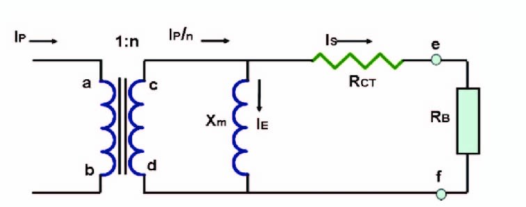
Primary current is zero as jghrist indicated, but voltage will rise and the assumption the bus is de-energized is invalid. The assumption that CTs always deliver ratio current is also incorrect. It is important to know the excitation curve above was generated with an open circuit primary while applying voltage to the secondary. I find an equivalent circuit is helpful:
CT_f5h69y.jpg

The excitation curve shows the non-linear characteristic of the magnetizing reactance labeled Xm in the circuit.
 
Status
Not open for further replies.

Part and Inventory Search

Sponsor