sparkview
Electrical
- Nov 12, 2015
- 59
Hi all,
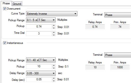
I am currently helping a colleague to determine a ground fault that tripped one of our 13.8kV outgoing feeders. This feeder is protected by a VAMP 140 overcurrent and earth fault protection relay. Based on the how the current settings of the relay it seems that the Earth fault protection was not accurately programmed during commissioning. Therefore, we would like to verify the settings and simulate in ETAP. The feeder being protected is a 2/0kcmil, 3/C, 15kV, CU cable with a distance of about 2KM and connected to a 13.8kV/ 480V step-down transformer downstream. What we would like to know of the Earth fault settings are accurate or is requiring changes and how is this value calculated. Below is a single line diagram illustrating the system and current settings in ETAP. Phase CT ratio is 100/1 and Residual Ground CT ratio is 50/1.
In advance many thanks for your support and if additional information is required please advice.
Regards,
Jairo