Continue to Site

Eng-Tips is the largest engineering community on the Internet

Intelligent Work Forums for Engineering Professionals

  • Congratulations IDS on being selected by the Eng-Tips community for having the most helpful posts in the forums last week. Way to Go!

IPO breaker with 3 trip coils in series 1

Status
Not open for further replies.

thermionic1

Electrical
Nov 30, 2018
314
I was doing a drawing review and saw something that caught my eye. A 345kV IPO breaker (intended for 3 ph tripping) that had the trip coils of all three poles wired in series. I checked the OEM drawings and this is how it came from the factory. I could not find the nameplate to verify trip coil voltage or resistance.

At first glance, I could see many things that could go wrong with this scheme, with few benefits. It's clear that changing a few jumpers would make parallel trip paths possible. I've seen instances of where a lower voltage coil was used to improve operating times, but don't recall it looking like what I saw.

Has anyone else seen something like this?
 
Replies continue below

Recommended for you

No, but if the coils are all rated for 1/3 voltage they have to be connected in series. What's your DC voltage and what are the coil voltages?
 
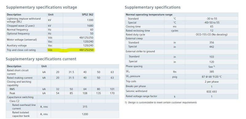
The nominal battery voltage is 125VDC. We speculated on the coils being rated lower, BUT, what if IPO or (sync close/trip) is required later? Install new coils? We are awaiting nameplate data back, so I don't have the coil ratings available at this time. This is a unique project for as as we have taken over from another firm after 5 IFC revs halted construction.
 
I'd want them in parallel, and that might be the manufacturer's standard. If the IFC packages were that bad the breaker specs might have been all fouled up as well.
 
It's been many years but I seem to recollect seeing that, three 42v coils and "a" switches in series. Sorry, it didn't raise any eyebrows. A potential advantage is that a failure of one coil's path would result in a breaker failure, which might be better than standing with a random 2 poles open while you wait for that breaker failure operation. It makes the breaker an all or nothing device in that regard. None of this would prevent equipping the breaker with additional 125v coils for single pole tripping/reclosing on SLG faults.

Bill
 
Connecting three trip coils in series seems to be preferred arrangement in US, as per the textbook 'Protective Relaying' by J. Lewis Blackburn.
The reasons cited are - easier monitoring of circuit continuity and requirement of less trip current.
 
Hi,
I haven´t come across this type of tripping arrangement. However it is mentioned in the IEEE document "Relay Trip Circuit Design". Apparently it is a public document and you can download it from here:
Reading the document, it looks as if the use of trip coils in series is (or was) a common design in Gas Operated Independent Pole Breakers. However I am not sure if the use of this type of devices is widespread in new installation nowadays (the document dates back to 1999).
 
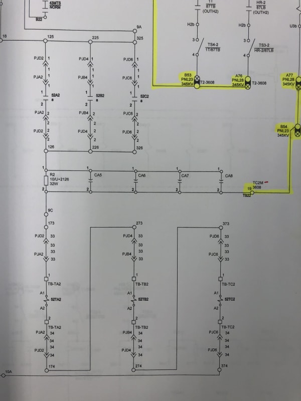
Thanks for the input. Please see attached pics for more detail. Another thing that bothers me is the placement & parallel configuration of the 52a contacts, intended to break the trip coil current.

The coil shown in the upper right is the TCM input to the SEL-451 breaker failure relay. The upper left is the trip path through the 43 Maint Sw @ the breaker through the parallel 52a contacts. The dwg shows TC2, but TC1 is the same. All 14 GCB's have the same internals for this breaker and a half station. It sure looks like converting over to parallel coils and series 52a contacts / phase would be easy to change, almost like that is what it should be.

I just don't recall seeing a design like this before. You go through enough breakers and other than fancy applications like sync close, most trip circuits are fairly similar. It's the odd balls and all that Human Performance Training / Questioning attitude that draws my attention.

It may have been popular to have trip coils in series in the time of OCB's and huge trip coils, but most coils that I see in new gear is about 6A @ 125 / phase (~20-25 Ohm). I remember an old GE Magneblast that had something like 50A DC in the close solenoid and what a PITA it was to test in the shop.

I keep thinking unnecessary breaker failure operation, but perhaps as mentioned, that is the intent.

What about a trip and one of the 52a contacts fails to open and 3 trip coils fry and maybe a set of protection relay contacts weld along the way? It's clear not everyone knows about unlatching trip on digital relays :)


3_coils_ko5dyv.jpg


snip-ratings_xwxzpf.jpg
 
Status
Not open for further replies.

Part and Inventory Search

Sponsor