Continue to Site

Eng-Tips is the largest engineering community on the Internet

Intelligent Work Forums for Engineering Professionals

  • Congratulations IDS on being selected by the Eng-Tips community for having the most helpful posts in the forums last week. Way to Go!

Is a VFD a source of electrical power? 1

Status
Not open for further replies.

veritas

Electrical
Oct 30, 2003
467
I have a question relating to SKM's PowerTools:

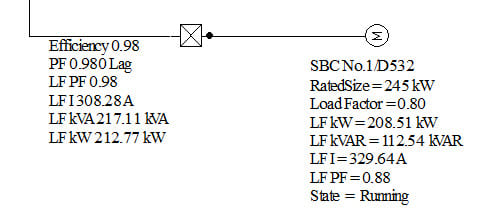
The following are the PowerTools loadflow results for an induction motor with its VFD:
VFD_z2m6tr.jpg


The motorside kw differs from the lineside kW by the VFD efficiency. So far so good. However, the power factor is different on both sides and so the kVAR and consequently the kVA is different. Line side kVA is 217.11kVA whilst motorside is 236.9kVA (sqrt[208.51^2 + 112.54^2]). So what has happened to the 19.8kVAR? I would have expected the total apparent power on both sides to be the same (minus internal losses)? Surely the VFD is not a source of electrical energy?

I have directed this to our local SKM tech support but he's off sick currently.
 
Replies continue below

Recommended for you

To be honest I don't see anything wrong with that. The VArs for the motor have to come from somewhere, but since VArs don't do any actual work, I don't see the issue in the apparent power on the load side being higher than the line side.

I can see the expectation that apparent power should be the same (or slightly less) on the load side of the VFD, but as far as energy is concerned, the watts on the load side are lower than the line side, which is correct. The losses in providing the VArs for the motor are accounted for in the efficiency of the VFD, there's no other energy penalty to provide them.

EDMS Australia
 
Yep, expect the VFD to have a higher input kW than the motor as well as a noticeably lower kVar input. The power electronics can readily provide the operating excitation current from the input kW.
 
You can consider the motor side of the VFD and the supply side as being two distinct systems with a DC link between them. Reactive power can't cross the DC link, so whatever the reactive demand of the motor might be, it needs to be met by the inverter part of the VFD. The rectifier of the VFD typically presents a reasonably high PF.
 
I think I've just answered my own question. It has to do with the capacitors in the VFD. In effect the caps in parallel with the motor is the same as a shunt pf correction unit. When I see it in this light it all adds up. The caps draw leading current which counters the lagging motor current. The sum means a reduction in source current and if I add the cap KVA to the motor KVA then I get a reduced source KVA. Confirmed this with a quick PTW study.

It is because of the caps that the VFD has such a good pf = 0.98.

So all good - unless I've gone seriously off the rails somewhere?
 
There is one thing to consider; the difference between definitions of PF. We are used to the PF = P/S = cos(phi) definition. And that applies to the Cos(phi1), where only the fundamental is considered. That does not apply to a non-linear load, like a VFD with its usually not sine shaped input current.
There, the P/S values differ (more S) from the sinewave values. That is why most (serious) VFD manufacturers used the Cos(phi1) in their catalogues. Some used to have the Lambda (Greek L) symbol for the P/S definition. But that practice is more and more rare in today's catalogues.

But, you are right, the DC link capacitors serve as a reservoir for the excitation energy, which is "borrowed" and paid back again once every motor frequency cycle.

Gunnar Englund
--------------------------------------
Half full - Half empty? I don't mind. It's what in it that counts.
 
Hi veritas,

The DC link capacitors don't directly compensate the motor PF.

The VFD comprises of three sections: the rectifier, the DC link, and the inverter: the motor reactive power requirement is handled by the inverter stage, with the inverter behaving as a synthetic source which more-or-less mimics the sinusoidal waveform of the utility supply, but with variable voltage and frequency.

The DC link capacitors don't draw a leading power factor in the manner that an AC capacitor does - instead they draw current in a series of peaks which are nearly in phase with the voltage waveform peaks, resulting in a high displacement PF: this behaviour is typical of most rectifier loads, regardless of whether the load is a motor or not. Only the active power required by the motor can cross the DC link - there's no such thing as reactive power with DC - and so the motor reactive current is confined solely to the inverter (output) stage of the VFD, the motor, and the interconnecting wiring. There's no simple relationship between the motor reactive current and the rectifier input current.
 
ScottyUK is right, but the way I put it to those who question it is that the DC bus caps are “in effect” correcting the power factor of the motor.

I also find it simpler to assume the total PF of the VFD itself is .95 instead of .98 in order to account for the distortion PF. You will find that most VFDs list it that way as well.


" We are all here on earth to help others; what on earth the others are here for I don't know." -- W. H. Auden
 
Status
Not open for further replies.

Part and Inventory Search

Sponsor