Continue to Site

Eng-Tips is the largest engineering community on the Internet

Intelligent Work Forums for Engineering Professionals

  • Congratulations cowski on being selected by the Eng-Tips community for having the most helpful posts in the forums last week. Way to Go!

Is it logical to use slab rebar in calculating negative reinforcement of a T-beam? 5

Status
Not open for further replies.

NewbieInSE

Structural
Dec 19, 2019
234
Hello all,
Slab requires reinforcement as it supports the loads above it. If I provide reinforcement for slab 10mm@8" at the top to meet the requirement, can I take the full advantage of this slab reinforcement in calculating the T-beam rebar adequacy of an existing RC beam?

I feel like I designed and provided the reinforcement which is required for the slab. Now if I give it as a loan to beam, then where is the reinforcement of the slab to cover its own stress.

Thanks.
 
Replies continue below

Recommended for you

The slab often won’t need it in the vicinity of the beam, so if you want to be cheap you can give the unused area of reinforcement to the beam. Note that sailing close to the wind like this can get you into trouble down the track.
 
Thank you Tomfh.
I'm actually checking an existing structure. So trying to avail of whatever benefit can be possible. T-beam gets about 30" each from its right and left slabs.
Should I subtract the slab required reinforcement from the provided reinforcement, and add the surplus to the beam moment capacity?
 
The purpose of T-beams is to connect a slab into a beam, providing a "wide-flange" T-beam shape, which acts compositely. You do not design them separately. In the main load-carrying direction (one-way slab action is usually expected in one direction, and the other direction is given 25-50% of the main direction rebar), you design the beam and slab flange as one unit to resist the loads. If the neutral axis is inside the slab (sagging, i.e., slab in compression), the calculation is simple, while neutral axes in the web require superposition; the procedure is found in any RC design book, and you probably know it. The same principle is followed for hogging (slab and possibly web in tension), and the strength is calculated once again by strain compatibility.
 
Newbie,

If you the slab doesn’t need the steel then yes it can be counted towards the beam. If you are checking existing slab then you should count it.

Also as centondollar points out, the slab and beam are generally one and the same in these so called “T-beam” zone, and thus “slab reinforcement” and “beam reinforcement” can be an artificial distinction.
 
Thanks both.
In FEM, In order to consider slab reinf to contribute wholly the T beam, I think slab's bending stiffness should be made zero.

Otherwise if slab resists some moment, and beam resists the rest, then both of them need to be designed for the share of stress they are under, and contribution of slab rebar to the T beam hogging reinforcement cannot be counted. This is my understanding now.

Is this ok, do you wanna add something to it?
 
Another question is, if i consider the slab as an integral flange of the beam and design both of these altogether to get the reinforcement, then does one need to design the slab separately once again for the surface load it supports? Using the conventional slab design methods e.g.,coefficient method, yield line etc.
 
It is common to design the slab separately, with the beams being support points.

Do you have a sketch to indicate the situation you are talking about?
 
ACI 318 Section 24.3.4 says to place part of the beam negative moment reinforcement in the slab over the minimum of the effective width or the clear span / 10. You might use that to justify using some of the steel in the slab in the beam strength calculation.
 
Most design guides actually recommend placing some of the beam reinforcement in the effective flange width for crack control as the slab beside the beam will crack without it.

But they usually suggest only bars within 2 bar sizes of the beam bars be included.

And any reinforcement outside the beam web is in included in the beam shear calculations.

If analysed with FEM, any moment within the effective flange width is Beam Moment (T Beam) not slab moment!
 
Thanks all.
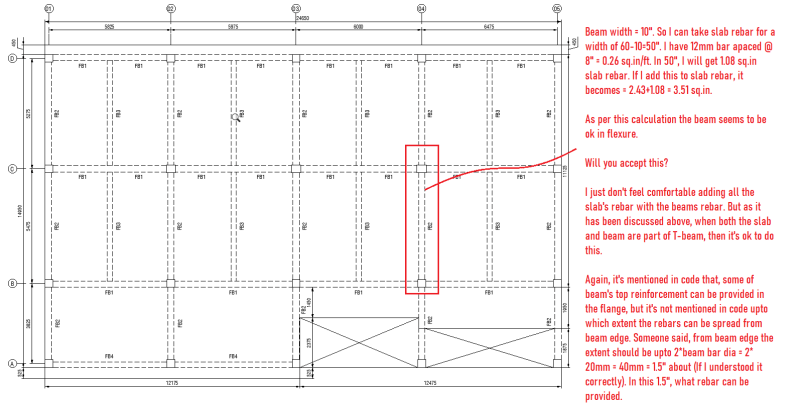
Please see the following figure.
At the marked location of beam, it requires 3.5 sq.in rebar at top. The beam reinforcement is computed considering the nearby slabs won't resist any load effects by it's nending stiffness. Provided reinforcement at that location is 2.43 sq. in.
The effective with of the T-beam is 60".

T-beam_issue_rldz31.png
 
All codes I know of define the Effective Flange width of a T-beam. You obviously do not understand the concepts.

I think you need to talk to your supervisor. We cannot do any more.

 
NewbieinSE said:
Thanks both.
In FEM, In order to consider slab reinf to contribute wholly the T beam, I think slab's bending stiffness should be made zero.

Otherwise if slab resists some moment, and beam resists the rest, then both of them need to be designed for the share of stress they are under, and contribution of slab rebar to the T beam hogging reinforcement cannot be counted. This is my understanding now.

Is this ok, do you wanna add something to it?


Newbie,

It's a good catch that you shouldn't accidently double count the slab stiffness and strength in the model. This depends on how you've modelled it, but I have certainly seen situations where people model in a beam with the properties of the combined T section as a beam element and then also supply plates for the slab going to the beam centerline and accidentally double count through the T section.

There's a number of ways you can do this, which will depend on your software, but your instinct is correct.
 
Oh, but yeah, you can't just arbitrarily take the full slab width as the Tee or anything like that. A limited width defined by code is part of the beam, then everything outside of that is still being designed as a slab. You also still need all the slab reinforcement designed as part of the slab in the area perpendicular to the Tee beam.
 
Based on the plan view above, the slab doesn’t look like it would need a great amount of top reinforcement within the flange of the T-beams.

Newbie, how are you assessing the amount of steel the slab itself requires?
 
THLS said:
You also still need all the slab reinforcement designed as part of the slab in the area perpendicular to the Tee beam.

Including the slab area within the T-beam flange zone? This is where it gets a bit murkier!
 
In the AASHTO bridge design spec, it's fairly straightforward - the slab spans between the beams, and the beams, including the effective flange width spans between the beam supports. Of course, in bridge superstructures the contribution of the slab by itself to the strength of the system would be small.

If the beam is shallow, and you wanted to count the slab contribution, it would make sense to add the contribution of the slab that's not included in the effective flange for the beam.

FYI, in the AASHTO standard spec the effective flange width is either the girder spacing or 12 times the thickness of the slab, whichever is smaller. In the LRFD spec, the effective flange is equal to the girder spacing, not limited to 12*ts.

Rod Smith, P.E., The artist formerly known as HotRod10
 
Thanks all for your help.
rapt, I understand the effective flange width. I might have said the effective flange width 60" in the example i gave, which might be in disagreement with the dimensions shown in the drawing. I picked the 60" just for pointing out the issue, i didn't back it with the layout i supplied. Sorry for the problem.
TLHS, Tomfh. Yeah, a limited slab width will contribute. So pls assume that I have taken that limited code specified slab width in the calculation shown above. Now is the approach i have shown above correct? Thanks.

Tomfh said:
Including the slab area within the T-beam flange zone? This is where it gets a bit murkier!
What would you do in this regard? In new design, I wouldn't consider T-beam action, just rectangular beam, and design it that way. and for the slab I would design it following the conventional methods or in the FEM.
But for this particular case where I'm trying to show a beam's capacity adequate (if it is), I'm considering the slab reinforcement (for the specific width as per code)with the beam top reinforcement.

Thak=mk you all for your efforts.
 
Tomfh said:
If the slab doesn’t need the steel then yes it can be counted towards the beam. If you are checking existing slab then you should count it.

The slab requires about 0.07 sq.in reinf (for hogging momenet), but provided reinf. is 0.26 sq.in. In that case, as per your understaning, 0.2 sq.in surplus reinf. (per ft. of the flange) could be added to the beam reinf.


Newbie said:
Now is the approach i have shown above correct?

If the steel is within the flanges then it will contribute to ultimate moment capacity. Personally I would count it if you are checking an existing structure.

However as discussed you should probably check the slab still has sufficient capacity after deducting the area of steel that you allocated to the beam. It will likely be ok, as the slab is so close to the beam in these locations.

Newbie said:
In new design, I wouldn't consider T-beam action, just rectangular beam, and design it that way. and for the slab

You should consider T-beam if there is a slab attached, as that is how it will behave.

Edit: I wrote this post prior to seeing your last reply. It sounds like there’s enough steel…. How did you assess the slabs required steel area?
 
Status
Not open for further replies.

Part and Inventory Search

Sponsor