Continue to Site

Eng-Tips is the largest engineering community on the Internet

Intelligent Work Forums for Engineering Professionals

  • Congratulations KootK on being selected by the Eng-Tips community for having the most helpful posts in the forums last week. Way to Go!

Is it Possible to Create a System Curve in EPANet? 1

Status
Not open for further replies.

Steven - Civil

Civil/Environmental
Jun 26, 2019
6
I'm trying to generate a system curve from EPANet. I found a reply by Fel3 explaining how to do this here:
The problem is that my "Discharge" node has a base demand of -1 and I'm getting a "system ill-conditioned at node Discharge" I think it's because there's no reservoir going into the node. If I do put a reservoir there, only the pipe between the Discharge node and the reservoir actually gets any flow at all. So maybe I'm misunderstanding Fel3's post, but for me it doesn't seem to be working. Is there something I'm doing wrong or a better way to generate a system curve?

One thing I was thinking was just to put a pump in place of the nodes and run it at different HP's. Couldn't the system curve then be generated from the total losses + elevation head differences at each flow?

Thanks for any advice! Model is attached
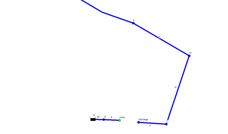
Image_of_Pump_Simulation_zqlucp.png
 
Replies continue below

Recommended for you

Steven....

Each disconnected part of a water model needs its own boundary condition, meaning a fixed HGL at a tank or reservoir. Without a fixed HGL, there is no way to completely solve the network because there is nothing to tie the system HGLs to.

The smaller portion of the model looks right (reservoir--pipes--pump suction), but the larger portion of the model is missing its reservoir. But, the reservoir needs to be at the far end from the pump (e.g. Node 1), not at the near end per your post. The larger system needs to be pump discharge--pipes--reservoir.

Fred

==========
"Is it the only lesson of history that mankind is unteachable?"
--Winston S. Churchill
 
Steven....

I have attached a model I built last year as part of training a young engineer in the fine art of pumping station design. The model consists of an EPANET file and an EXCEL spreadsheet. For EPANET, I included both the .inp and the .net files because it's easier to read the Project Summary in the .inp file (it's just a text file). You can run the .net file directly, but you can also edit the .inp file and start from there. The model duplicates fairly closely what I explained in the thread you referenced above. The model generates system curves for one pump operating alone and two pumps operating in parallel.

The procedure is pretty simple:
-- Edit the EPANET file to suit, then run it.
-- Take the HGLs for the nodes representing the pump suction and pump discharge and copy them into the spreadsheet. This will automatically plot the system curves.
-- Add the design point and the pump curves (my spreadsheet has room for two pumps, but you can add more) and you are done.

I hope this helps,
Fred

==========
"Is it the only lesson of history that mankind is unteachable?"
--Winston S. Churchill
 
 https://files.engineering.com/getfile.aspx?folder=f07a001a-1301-47dc-8a36-68724dae5496&file=FEL_Simple_Pumping_Station_(spreadsheet).zip
Status
Not open for further replies.

Part and Inventory Search

Sponsor