roldy
Aerospace
- Sep 3, 2012
- 54
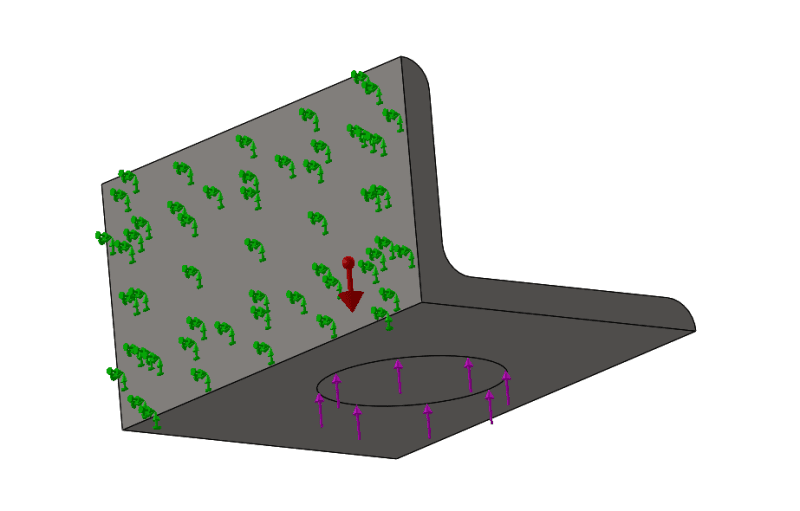
I'm not too familiar with using the SolidWorks simulation tools and would like some feedback on these setups. The first simulation has a 56,000 lbf load applied upwards to a circular region on the bottom face of the L angle. The second simulation has a 56,000 lbf load applied to a region of the edge 2.25 long. I applied it to a point on the midline, I'm not sure this is correct. Green arrows have a fixed condition. Load is applied in the area of the circle shown on the bottom face.


