Eng-Tips is the largest engineering community on the Internet

Intelligent Work Forums for Engineering Professionals

Is there any hand calculation vs FEA modeling Lifting Lug for Steel Alloy 2

Status
Not open for further replies.

tatox

Structural
Jan 2, 2004
15
0
0
ID
Hello there

I usually design steel lug hanger using AISC or EN 1993-1-9_2006 EUROCODE 3.
I have checked that the eurocode or the aisc is sufficient for tension plane failure, single plane failure, double plane failure. The safety factor is sufficient
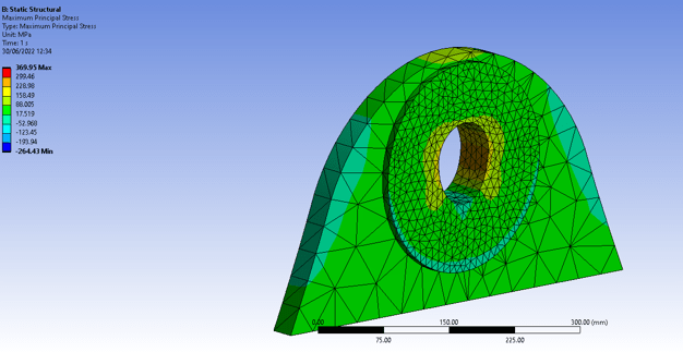
However when i checked it with 2D 6-dof plate-shell FEA for linear analysis, the von misses is greater that lets say 55%-60% of yield, which the allowable stress load.
Maybe my load pressure is false, i checked the bearing load femap example for 2D, looks fine.
Hope there is someone who already compared the fea lug model with hand calc analysis as examples (book also preffered). any code is alright, AISC, Eurocode3, ASME or Stress Analysis Air force.

Regards

vendor1_bvu4su.png

connecting plate by vendor
m70_op7g3g.png

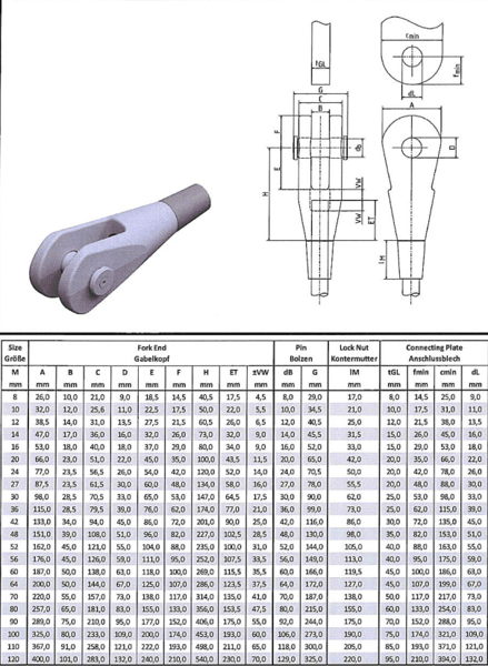
m70 hanger, recommended plate 50mm thick S355
load_hbrbqp.png

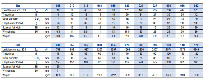
ultimate load max EC3 is 1663kN, i suppose we have a load between 750kN to 997kN (0.6 Ultimate), and stress still in service allowable condition
 
Replies continue below

Recommended for you

your peak FEM stresses are at 90dg ? (taking 0deg as axial, as the load direction)

This seems like some of the "madness" of today's world .... you do a hand calc, GTG, less load than the hanger allowable (by a sizeable margin) but still people want an FEA ??

You'll spend a month of Sundays trying to get the load on the bore correct. What are you doing now ? Radial pressure ?? over a portion of the bore ? +- 60 degrees arc ? 45 degrees ? 30 degrees ?? cosine distribution ??

"Hoffen wir mal, dass alles gut geht !"
General Paulus, Nov 1942, outside Stalingrad after the launch of Operation Uranus.
 
Load is straight up. no degrees.
I did simple 2D plate analysis with bearing load implementation (see Exercise 15 - Bearing Load - Rev F.zip from F3m4p) or parabolic distribution radial like in SW help Bearing load distribution.
the vendor did with solids, maybe radial pressure or contact with the pin. Seems the solids have lower stress than my shell model, but it is still beyond allowable stress 55%-60$ yield.
If i do the nonlinear analysis maybe the stress higher and more spread.
The clients want it done in FEA also as their check. I can't increase the thick of the connecting plate, since the fork mouth width is given.

The approved stress is based on von mises that should lower by 55^-60% yield right? or can be higher since it as bearing stress?
 
"Load is straight up. no degrees." ... yes, that's what I meant by "0 deg" ... axially loaded.
can you show a better view on the bore of the hole ? It looks like the peak stresses aren't where you'd (I'd ?) expect.
Your FEA is predicting stresses above yield ?

The approved load probably comes from testing.

"Hoffen wir mal, dass alles gut geht !"
General Paulus, Nov 1942, outside Stalingrad after the launch of Operation Uranus.
 
The code equations probably include local yielding effects.
And probably use stress concentration factors which come from test data.
As rb says, getting a FEM to match empirical lug data is not easy as there are lots of subtle effects - clearances, contact surfaces, local yielding, etc which need to be accounted for.

I would question your customer as to why they need the FEA and why they think that is better than the code analysis.
 
I will re check my FEA plate.
The FEA in here is a required for stress-related especially for bridge hanger.
i found hand calc vs FEA here: looks like i need to check pin-hole fit relation, E pin/E plate relation, stress increasing factor hole to width plate. hole to thick plate from Petersen Book.
Well i got 450 MPa for connecting thick plate recommended by vendor for ~997 kN, for S355 steel plate by hand plain 50mm thick plate.
I got around 360 MPa for 751kN force in my FEA with thickening plate 50mm welded to 36mm plate.
So if it said ok by ASME or AISC, but it has local yielding in FEA, so any thought?
 
is the yielding under an ultimate (factored) load condition? or under a fatigue / service load condition? definitely do not want any yielding at or near fatigue / service loads.
 
Just a couple of pointers when it comes to analysis of lugs that can have an effect on stress level accuracy. For FE, ensure the mesh density is sufficient local to the regions of high stress. Consider the effects of hole clearance. With a tight tolerance, the contact angle w.r.t the lug axial direction (your case vertically) is generally considered to be +/- 90deg. That will reduce with hole clearance. If you consider your clearance to be appreciable, it may be worth considering having a look at the contract angle using the Hertzian contact method. Another thing, pin bending may have an effect on the contact bearing pressure distribution through the lug thickness. This is affected by pin size (diameter), material moduli, lug / clevis thicknesses (bearing contact lengths) and gap size. The question is, when it comes to analysis modelling, to what level of accuracy, or even simplifying assumptions, is considered acceptable for the joint being considered?
 
all those points are reasons for me why not to model lugs.

very fine mesh ... sure, but it'll detect stresses that hand calcs resaonably gloss over.

contact angle ... there's a thesis project on it's own.

clearances ... another project.

my 2c ... don't model the pin, just model the loading.

I do find it funny how different industries consider FEA. Some (like auto) have FEA built into the contract, as though it is a cure-all, superior to hand calcs. My industry is all about "validate your FEA" (as though FEA is the more questionable route, compared with hand calcs) most often with a hand calc, maybe some (questionable) strain gauging, maybe some "weasel words"

"Hoffen wir mal, dass alles gut geht !"
General Paulus, Nov 1942, outside Stalingrad after the launch of Operation Uranus.
 
Although the aim of the hand calc and the FE analysis are the same, the way they get there are two different worlds, and to try and compare will be very difficult. As other posts have said, there are simplifying FE approaches that may help. Good luck, it’s not an easy task!
 
It seems that you have a course mesh on the outside and a fine mesh near the hole. Are the parts meshed together or is there some "glued" parts involved?

Based on the colours alone you seem to have low stresses except for a (probably) very local peak stress of 370 MPa. Is that the stress that concerns you?
 
ASME BTH is the most thorough standard I've seen for pinned lifting connections, it references papers where the calculations are compared to test results.

Anyone who knows what they're doing solves these problems with hand calculations.

To do this with FEA would require the clevis, pin and the lug to be modelled with non-linear contacts and materials. The assessment would be based on plastic strain and collapse load. Any FEA assessment based on von mises for this problem is nonsense.
 
@ThomasH @SWComposites (
yes, they want 0.6 fy max. with yield is 355 MPa means only 213 MPa max for service load. This is beyond that.
@Stress_Eng
Since the pin and the fork is given for the design load, then for structural designer only checks the gusset plate that in designer area, while it cannot bigger than the fork mouth.
@SSCon @rb1957
To model itself as pin contact will need a full blown FEA, and more time. Me would like to test with simple FEA like SAP, Midas, or even STAAD. So basically is a loaded gusset model. if it need non linear material, is fine. but contact will need another big full blown FEA.
ASME BTH-1 2017? let me check it, because my self is civil engineer not familiar with ASME. It usually for temporary lugs right, not a permanent like a bridge hanger.
I think the petersen's Book that used in FEA lugs hand manual use several stress concentration nomogram factor that not included on standard pin-lug AISC, Eurocode. maybe even ASME BTH.
Those factors (i think) shall be calculated as shown also in in STRESS ANALYSIS OF A LUG LOADED BY A PIN by defence military australia, STRESS ANALYSIS MANUAL, or some paper : [Just found it after reading petersen book]
while those stress factors i can't found it in code yet.

-----------
Looks like i need go to non-linear analysis since it beyond yield. Just found out that non-linear analysis maybe corrected the result so it can below yield. That in web said the linear analysis is about the same as petersen book. but the non-linear analysis can reduce it because Neuber plasticity correction. Correct?
Need to study Neuber plasticity ....
 
"Me would like to test with simple FEA like SAP, Midas, or even STAAD. So basically is a loaded gusset model. " so you want to analyze with an overly simplistic cheap FE model? for a presumably safety critical lifting/hanger lug? And you are going to believe that FE result over code based hand calculations that presumably are set up to account for actual lug behaviour? This is IMO just so wrong.
 
Why don't you knock it off with them negative waves?
Why don't you dig how beautiful it is out here?
Why don't you say something righteous and hopeful for a change?

"Hoffen wir mal, dass alles gut geht !"
General Paulus, Nov 1942, outside Stalingrad after the launch of Operation Uranus.
 
Status
Not open for further replies.
Back
Top