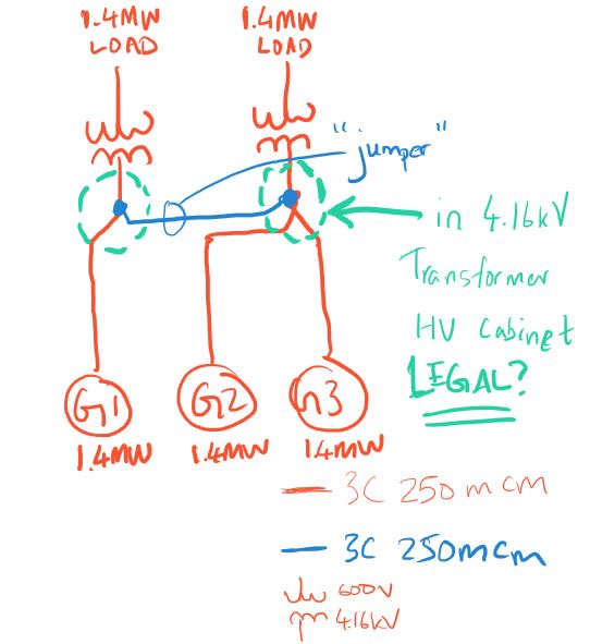
I'm attaching a sketch to make it 100% clear what I am trying to do. See attached JPG.
This is for an 8 month rental project where they are renting generators and are looking to parallel the 3. There is no space for a new switchgear / 'splitter' to tie the 4.16kV connections together.
Someone brought up the idea of adding a jumper cable between the two transformer HV cabinets, to tie the 4.16kV sides together.
I've never seen an arrangement like this, but I can't find any rules/code violations either. This is located in Canada, but I'm open to NEC applications and code rules if there are any.
I've verified that the transformer and transformer bushings can withstand the short circuit contribution from the 3 generators.
I've verified that the 4 hole nema pad on the HV bushings are good for the FLA of 2x generators (most that any bushing will see).
I've verified that the 250MCM cables are all adequate in terms of carrying the expected load currents and can withstand the short-circuit currents as well (generator protections trip quite early).
But I just can't wrap my mind around the fact that this is an unorthodox arrangement, and I'm looking for code rules that discuss:
- tap conductors
- using the HV cabinet as a JB/raceway even though the 4.16kV cables are all terminated within
- any other rules?
Would like to beef up my argument for this arrangement if I do go ahead and submit it to the local inspection authority for approval.

