Eng-Tips is the largest engineering community on the Internet

Intelligent Work Forums for Engineering Professionals

Is this an in-plane discontinuity in vertical lateral force-resisting system? 3

Status
Not open for further replies.

milkshakelake

Structural
Jul 15, 2013
1,106
2
38
US
Is this an in-plane discontinuity in the seismic system? Here's what my framing looks like:

Vertical_lateral_system_elevation_2023-08-07_133106_whb3l3.png


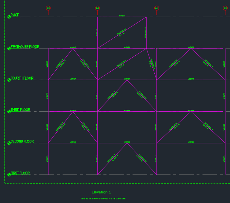
I know it's not the best, but I did this years ago. Now it's under audit and a regulator is saying it's a vertical irregularity, which I tend to agree with. However, I would like to defend myself. From my understanding, a vertical in-plane discontinuity would impart overturning moment-load-transfer discontinuity. This would require amplified forces for the columns and the collectors (horizontal link connections between bays).

In this case, I'd say that the entire vertical lateral system is one big truss, so there is no discontinuity. I'm not sure how I'd justify that reasoning or if it makes sense, so I'm looking for some guidance.


For context, the applicable code is ASCE 7-10, seismic category is B, and the following code applies:

Table 12.3-1. In-Plane Discontinuity in Vertical Lateral Force-Resisting Element Irregularity: In-plane discontinuity in vertical lateral force-resisting elements irregularity is defined to exist where there is an in-plane offset of a vertical seismic force-resisting element resulting in overturning demands on a supporting beam, column, truss, or slab.

12.3.3.3 Elements Supporting Discontinuous Walls
or Frames - Columns, beams, trusses, or slabs supporting discontinuous walls or frames of structures having horizontal irregularity Type 4 of Table 12.3-1 or vertical irregularity Type 4 of Table 12.3-2 shall be designed to resist the seismic load effects including overstrength factor of Section 12.4.3. The connections of such discontinuous elements to the supporting members shall be adequate to transmit the forces for which the discontinuous elements were required to be designed.


For some justification on my thought process, this situation is fundamentally different than something I found in 2012 IBC SEAOC Structural/Seismic Design Manual that explains this irregularity:

img002_srpuad.jpg


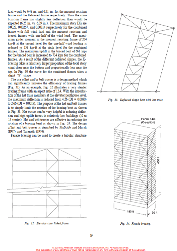
The fundamental difference is that the offset shear wall is not strictly connected to a direct vertical load path, whereas in my case, it's like a truss with staggered diagonal supports that all connect. My situation is more akin to what is described in AISC Design Guide of Low-Mid Rise Structures, showing a hat truss concept:

MARKED_UP_-_DOB_report_2023-07-13-2_m3iyyf.png


Sorry if this doesn't make a lot of sense, which is why I'm posting here.
 
Replies continue below

Recommended for you

This looks like a vertical discontinuity to me. I'm not sure I buy the "one big truss" argument as you don't have a direct load path to the foundation via bracing; rather, you're transferring load in and out of adjacent bays via collectors. Not sure classifying this as an irregularity would have impacted your design since I'd imagine you would have designed the collectors and columns for overstrength anyway, but I'd have to check if that's actually required in SDC B.

Edit: In addition to the in-plane discontinuity, it also looks like you may need to evaluate whether you have a weak or soft story at the 1st and 3rd levels.
 
Yeah, this could be a tough sell.

I don't know quite when it changed but, back in the day, ASCE 7-05 used to say that the irregularity required the offset to be greater than the length of the VLFRS element being offset. One might argue that the spirit of that was the notion that the offset would only be a concern if it caused load to be passed through parts of the gravity system that would not, conventionally, be designed for primary lateral load effects. Perhaps you could argue that your setup also does not pass primary lateral load effects through gravity only framing?

Unfortunately, even if you could make hay with that argument, the last sentence about stiffness might still trip you up.

All of this is a reach, including referencing an antiquated code edition. This is me pulling out all of the stops to help a colleague.

c01_ajnhva.png
 
@Deker It is required to design the collectors and columns for overstrength in SDC B in this case. I didn't design it for overstrength.

Thanks for your input! I might just take the plunge and design everything for overstrength. It's already built, so it might be a bit of a problem and I might have to add bracing instead to remove any irregularities.
 
@KootK Thanks for pulling out that code bit! I'm not sure if it'll help because the regulator is relying on ASCE 7-05. And yes, that last sentence does destroy the whole argument because there really is a reduction of stiffness in some stories.
 
@KootK There is an intermediate reinforced masonry shear wall in the other direction, so it was designed for R=3.25. I generally design steel for R=3, so I could always fall back on that and do a separate R-value for this steel direction. It wasn't designed as concentrically braced frames with R=3.25 because of the additional stiffener requirements.
 
KootK said:
I generally design steel for R=3, so I could always fall back on that and do a separate R-value for this steel direction.

That's what I figured. The 7-22 commentary says that this is about protecting the gravity system from demand created by over strength in the lateral system. I feel that the logic in that rationale diminishes some when the lateral system is of such low ductility that you don't really even have explicitly designed locations of plasticity in he system.
 
I feel that the logic in that rationale diminishes some when the lateral system is of such low ductility that you don't really even have explicitly designed locations of plasticity in he system.

Agreed, there isn't really much of a place for a plastic hinge to form. Anyway, the code is the code so I'll probably do an overstrength analysis. It might not change anything anyway, it's just egg in the face (though well deserved) for doing a bad design in the past.
 
These are some excerpts/discussion points from a FEMA P-2012, "Assessing Seismic Performance of Buildings with Configuration Irregularities" that you may or may not find relevant:

FEMA P-2012 said:
Some irregularities (H2, H3, H4, V4, V8) and configuration requirements such as those for chords and collectors) reflect load path issues that are particularly sensitive to the specific structure, are usually associated with earthquake damage but not collapse, and are not well suited to quantification across a broad design space of archetypes.

FEMA P-2012 said:
In-plane discontinuity irregularity [V4]. The response parameters used in seismic design are based on continuous vertical elements of the seismic-force-resisting system with well distributed inelastic response. Where there is an in-plane discontinuity, overturning demands on the supporting elements may be much greater than those predicted by a linear elastic analysis using forces reduced by the response modification coefficient, R.

FEMA P-2012 said:
The commentary figures in ASCE/SEI 7-16 should be updated using those from this document. In particular, the figure for V4 in ASCE/SEI 7-16 is incorrect as it reflects the definition of that irregularity in
ASCE/SEI 7-05.

FEMA P-2012 said:
Design Forces for Collectors and Connections [H1, H2, H3, H4, V4].
Section 12.3.3.4 of ASCE/SEI 7-16 requires that design forces determined in accordance with Section 12.10.1.1 be increased for connections of diaphragms to vertical elements and to collectors and for collectors and their connections, for systems with one of several horizontal or vertical irregularities. Considering the historical development of these irregularities and reasonably anticipated consequences, as detailed in Chapters 4 and 7, it is recommended to limit the extent of such increased forces as follows:
[...]
- For structures with diaphragm discontinuity irregularity [H3], out-of-plane offset irregularity [H4], or in-plane discontinuity irregularity [V4] increased forces need be considered only at levels with the irregularity and at adjacent levels above and below, due to possible load redistribution within the seismic-force-resisting system.
 
This seems very subjective, but to argue your side:
[ol 1]
[li]ASCE 7-10, Code Commentary Section C12.3.2.2 states: "Vertical lateral force-resisting elements at adjoining stories that are offset from each other in the vertical plane of the elements and impose overturning demands on supporting structural elements ... are classified as in-plane discontinuity irregularities." You could make the argument that there is no offset where the elements meet at the adjoining story.[/li]
[li]If the whole purpose of identifying this type of discontinuity and providing overstrength is to protect the gravity load carrying system below, I don't see the risk here unless you're relying on the beam at the penthouse level to support the column above. This doesn't seem to be the case, though, considering that you have diagonals below.[/li]
[/ol]

Somewhat related: suppose a multi-story building is shaped like a truncated pyramid with all of the exterior columns slightly sloped inward (let's say at 10 degrees from the vertical). Should this discontinuity apply to every column in the exterior walls?
 
I don't think the discontinuity in this frame is that pronounced or particularly egregious in terms of violating underlying ELF assumptions of uniform stiffness and distribution of nonlinearity. But if it's being flagged by an auditor then the "burden of proof" lies with you and you seem to be facing it head-on with humility instead of reacting with ego, so kudos to you for having a healthy attitude abotu it.
That being said, one analytical way to defend your design might be performing a scaled modal analysis. By doing so, you're 1) defending your design by showing it works as-is (potentially), 2) respecting the audit engineer, and 3) showing you're a badass engineer who knows how to do modal analysis :)
 
Both of you, thanks for the comments. I have pretty much resolved my course of action and I'm going to just do the overstrength analysis. I decided not to fight it, even though you have helpfully provided a path forward. I don't really see that this structure can fail in any way, but I'm also going to have a hard time justifying that it's not an irregularity. It's a reach at best, even with all the references and code snippets. Thankfully, I overdesigned the hell out of this thing, so I don't anticipate any problems.

I've taken away some lessons:
1. Don't stray too far from conventional design.
2. Treat every project like it's the most important thing in the world. Someone else in my office did this design, and I should've nipped it in the bud.
3. Overdesign lateral (which we did, so this reinforces it).

@Eng16080 If a building has exterior columns sloped, I think it would follow your point 1 that there is no offset. It would follow it a bit more closely than my problem.

@bones206 I'm not a badass engineer, more of a businessperson. I have no idea what a scaled modal analysis is. I'd be afraid that if I used it on the fly, it would cause further audits! I do agree that this arrangement doesn't violate much. For one thing, when we discuss stiffness, it's not as cut and dry as the number of braces at that level or a simple EI calculation. The "outrigger effect" or "belt truss" idea shows that stiffness in a lateral system is a holistic calculation based on all the interconnected pieces of a truss. However, I wouldn't want to dust off the FEM textbooks to figure out how to prove that to an auditor, who will start raising more questions about the methodology. The best ROI is to bite the bullet rather than save face.
 
Quick update, I decided to "fight" the objections and used all the code references y'all sent, and it worked! The thing that probably helped most is ASCE 7-10's definition of offset.
 
Yeah!!! Go team! In the constant battle between public safety and EOR well being, I come down resolutely on the side of the latter. Shhhhhh....
 
Status
Not open for further replies.
Back
Top