Continue to Site

Eng-Tips is the largest engineering community on the Internet

Intelligent Work Forums for Engineering Professionals

  • Congratulations IDS on being selected by the Eng-Tips community for having the most helpful posts in the forums last week. Way to Go!

ISO GD&T question 1

Status
Not open for further replies.

JohnStarling

Mechanical
Jan 25, 2018
5
Hi,

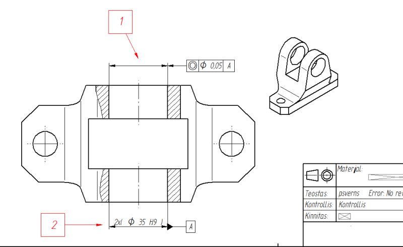
I have a part (a bracket I think is the best word in english to describe this part), which has two nominaly coaxial holes in it (please see the attachment). The holes are of the same diameter. I want to state that these two holes (Ø 35 H9) should be machined with one operation (for example G76 fineboring cycle), to a achieve good coaxility of the holes (a precision pin will go trough the holes).

I have uesd coaxility geo. tolerance (acc to ISO 1101) to make it work. But I have some questions.

1) On the drawing I set the axis of one hole (see annotation #2) as a base and the I attach the coaxility feature control frame to the axis of second hole. But beacause the holes have the same diameter, there is no point to show the diameter of the second hole again. So I use a blank diameter dimension line just to attach the coaxility tolerance (see annotation #1). Can I do this?
2) Is this kind of approach unabmiguous or can it be better done with some other tolerance (in ISO system)?

Coax_c6defi.png


Best regards,
JS
 
Replies continue below

Recommended for you

There is more than one way

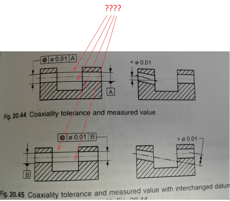
This is one of the possibilities:
The picture is taken from this book:
It contains several examples of controlling the coaxiality, too many to mention all of them here.

"For every expert there is an equal and opposite expert"
Arthur C. Clarke Profiles of the future
 
Hello CheckerHater,

Actually it turns out that I have the book you reffered to. The book contains also an example which is almost identical to my inital approch and now I can see that there is a ambigiuity problem with this rapprochment (see the attached pic). But the example in the book also raises another question:
Why are there these thin lines between the two holes (pointed with red arrows on the pic)? These lines seem to show that these holes somehow should form a single unit, but actually the tolerance itself states clearly that we have two separate axes, that we want to by as closely aligned as possible. I don`t get it...

Coax2_oerdns.png
 
Lines like that are optional. By themselves, they do not indicate any special requirements, unless actual GD&T/GPS control is applied.

Holes are considered 2 separate features, because (for example) even if they are machined "at once", body of part itself may experience binding from internal stresses, heat treatment, etc.

The reason I chose "datumless" example is that designating certain feature as datum somehow makes it more important then other(s), which is not the case. (This also may be my personal preference)

I hope that helps.


"For every expert there is an equal and opposite expert"
Arthur C. Clarke Profiles of the future

 
OP said:
I want to state that these two holes (Ø 35 H9) should be machined with one operation

I am concerned about your statement "machined in one operation". GDT symbols imply NO processing requirements. They really mean the part must meet drawing requirements when all processing is done and only apply at that stage of processing (not at some later assembly operation. See Y14.5-2009 para 1.4(o) page 8)

Secondly - avoid the use of Concentricity to control coaxial relationships due to the complex inspection requirements. Position is preferred.

Certified Sr. GD&T Professional
 
@ mkcski

1)
I know that GDT symbols imply no processing requirement.
But my own limited experience with turning and machining tells my that the best (easisest) way to assure good coaxility of these two holes, is to machine them in one operation (or at least the finishing cut). So my intent is to tranfer this idea to the drawing in a manner, that the shop producing the part would come to same conclusion. Of course in the end it`s always up to the shop, how they choose to produce the part, as long as the part meets the requirements.

2) I`m from Estonia, EU and here we mainly deal with ISO standards, in this case (as I stated also in the original post) with ISO 1101. And according to ISO 1101 the coaxiality has a litlle bit different meaning (an also simpler inspection process).

BR Peter
 
I guess you are OKAY on the shown concentricity on an ISO drawing. ASME will be the standard where concentricity is to be avoided.
I think you can use position in ISO because concentricity in ISO is just a particular case of position.

 
JohnStarling:

1) I am glad you appreciate the "processing" myth. I argue the "implied machining" point a lot in the classes I teach. Some have to unlearn old thinking. So be it.

2) Yes ISO is different, but not as much as you might think. ISO 1101:2017 para 17.14.3 states "extracted median line" of the datum feature must be found to establish the datum and measure Concentricity error. Y14.5 is the same. Median lines are difficult to establish at best. Comparatively, Position in your example, invokes the axis of the "associated integral feature" as defined in ISO:2011 paragraph 6.2.3 Figure 4. In Y14.5 terms, this is the axis of the "actual mating envelope" - (e.g, the center of an expanding mandrel). Food for thought.

Certified Sr. GD&T Professional
 
ISO - position tolerance controls location of extracted median line, extracted median surface or extracted (actual) center of the sphere. Since by definition extracted median line and extracted median surface are imperfect position tolerance has control over form of these derived features, thus over certain aspects of form of the feature of size.

ISO - coaxiality is nothing but position tolerance applied to nominally coaxial features of size, but it has a separate symbol (the same as concentricity symbol in ASME).

ISO - concentricity has the same symbol as coaxiality, but in addition the ACS modifier (Any Cross Section) is associated with the tolerance frame. This characteristic controls relationship between the toleranced feature and the datum feature in each cross section individually.

Credit to pmarc.
 
Hello,

A few comments to what has been said up to this point:

- I agree with CH that there is more than one way to tackle the problem, and although we don't know real application, I would agree that a "datumless" solution seems to be promising choice.

- The picture from G. Henzold's book is not really up to date with the most recent ISO GPS standards. ISO 14405-1:2016 (and previous 2010 version too) for "Linear Sizes" uses CT modifier instead of CZ. CT stands for Common Toleranced Feature of Size and is used in conjuction with size dimensions. CZ (Combined Zone) rather applies to geometric tolerance zones.

- The above does not mean that no other "datumless" solution for controling coaxiality of holes exists. Another option is to control location of the holes with a regular position tolerance relative to some datums AND apply additional extracted median line straightness tolerance with CZ modifier. In ISO such straightness callout would have power to control offset between "axes" of the holes. The straightness tolerance value would, of course, have to be smaller than the positon tolerance value.

- Concentricity (or as a matter of fact Coaxiality, if 3D features are considered) in ISO is nothing but a special case of Position used for nominally coaxial feautres, meaning that there is no geometrical difference between the two controls. This is different from ASME, where Position and Concentricity are two totally different animals.
 
Thank you pmarc

There is an opinion that CZ should only be used inside of FCF, and CT outside, although not everybody agrees.

And then there is also the concept of UF (united feature), so I am looking into the future with optimism :)

"For every expert there is an equal and opposite expert"
Arthur C. Clarke Profiles of the future

 
pmarc:

pamrc said:
2) Yes ISO is different, but not as much as you might think. ISO 1101:2017 para 17.14.3 states "extracted median line" of the datum feature must be found to establish the datum and measure Concentricity error. Y14.5 is the same. Median lines are difficult to establish at best. Comparatively, Position in your example, invokes the axis of the "associated integral feature" as defined in ISO:2011 paragraph 6.2.3 Figure 4. In Y14.5 terms, this is the axis of the "actual mating envelope" - (e.g, the center of an expanding mandrel). Food for thought.

I am reading the ISO standards as I can afford them. So I am operating in a "void" as far as interpretation. So, if you care to take the time, can you please tell me what I am missing regarding the "difference in establish datums" in my quote for an earlier post?

Certified Sr. GD&T Professional
 
mkcski,

That is strange, but in my version of ISO 1101:2017 in para. 17.14.3 I don't see the statement you quoted (why you wrote it was my quote is a different story ;-]).

Anyway, you seem to be talking about Concentricity which is 2D control and is not the same thing as Coaxiality in ISO. They both have the same symbol but Concentricity always go along with ACS modifier.

My point was that regardless if you use Position or Coaxiality tolerance, in ISO there is no difference because their geometrical interpretation is the same. That is not true in ASME.
 
17.14.3 Coaxiality specification of an axis
In Figure 165, the extracted median line of the toleranced cylinder shall be within a cylindrical zone of diameter 0,08, the axis of which is the common datum straight line A-B.

Figure 165, coaxiality indication: Shown a shaft with two bearing journals A and B and the middle feature is controlled with concentricity within Ø0.08 to A-B. page 106

I read and re-read mkcski posting and I could not figure out myself why he said the above quote is from pmarc ! Actually he said is from PAMRC not PMARC!
 
Sorry Guys. It was my text not pmarc's I repeated for convenience. Maybe this isn't kosher on the forum?

I am busy right now but want to respond after rereading pmarc's response and the ISO.

Certified Sr. GD&T Professional
 
pmarc said:
The straightness tolerance value would, of course, have to be smaller than the positon tolerance value.
Somehow loose related with the subject
Isn't this also true in ASME?
At least for positions modified at MMC and derived median straightness.
Thank you pmarc
 
Per para. 5.4.1.2 in Y14.5-2009 it is also true in ASME. I don't necessarily agree with that but this is the letter of law.
 
I must thank you all for these replys.

1) But it makes me wonder, if these GD&T rules (both acc to ISO and ASME) are maybe getting little bit too far from practical mechanical engineering applications. You guys all seem to have a solid understanding of the subject, but still there is hardly any consensus of how this fairly simple requirement should be stated and also the how to actually interpret the coaxility/concentricity tolerance (acc to ISO at least).

2) The essence of coaxiality/concentricity (in my personal opinion) is best explained in the comment of greenimi. This explonation is consistent with the ISO GPS Handbook (by H.S. Nielsen) that I just started to read:
*the tolerance zone of coaxiality is a cylinder (3D);
* the TZ of concentricity is a circle (2D) and thus needs the ACS (any cross section) modifier, because mosty we deal with 3D features (That saind,I´ve seen an example, where concentricity was used without ACS. The part had an engraving - two concectric circles - and these circles had to be, well.. concentric to each other. And beacause the engraving was show shallow compared to the diameters of the circles, then it could be considered almost as a 2D feature and thus no ACS was applied..)[The Geometrical Tolerancing Desk Refrence by Paul Green, p. 87]

3) @ pmarc
Figure 20.46 in G.Henzlod book uses CZ with straightness tolerance (which is a GT),so this should be still up-to-date? I also looked into the ISO 14405 standard and your right, there is this CT modifier, but at first clance I couldn`t find any example, how to use it.
 
Status
Not open for further replies.

Part and Inventory Search

Sponsor