Continue to Site

Eng-Tips is the largest engineering community on the Internet

Intelligent Work Forums for Engineering Professionals

  • Congratulations MintJulep on being selected by the Eng-Tips community for having the most helpful posts in the forums last week. Way to Go!

Item modular profile construction design - an advice is needed

elinah34

Mechanical
Aug 19, 2014
125
Hello,

I had almost a final design (1.xt, added to this post) and suddenly there was a need to use other castors with another (bigger) interface.
The new castor interface is very big, and from using only 1 screw I had to use 4 screws.
The Item profile end couldn't connect to the new castor and if I use a base plate between the castor and the profile end, the base plate will only be partially supported - looks bad.
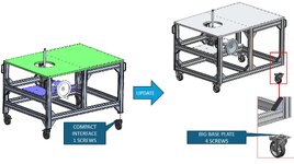
1.JPG
As a result I changed the design a little bit (2.xt, added to this post) and I lowered the lower beams to the minimum possible height.
The motivation was to support the new castor interface base almost fully (there is still an area that isn't supported) supported by the Item profiles.
I think the construction in this design isn't quite good as the former design... what do you think? is there any other elegant solution that will prevent changing my original design?
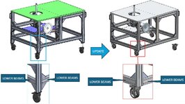
2.JPG
 

Attachments

  • 2.JPG
    2.JPG
    187.7 KB · Views: 2
  • Q.zip
    9.5 MB · Views: 0
Last edited:
Replies continue below

Recommended for you

I've done a couple different approaches, both worked for my needs at the time:

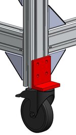
On your 1.xt version: cut a piece of heavy L-channel (angle) for a mounting bracket. Attach the vertical leg to your table leg, mount the caster to the horizontal leg. Bracket should be large enough for the caster flange. Alternatively, add a mounting plate between the horizontal leg and the caster flange.

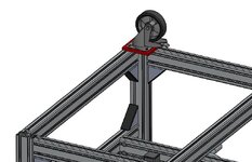
On your 2.xt version: cut a square / rectangular mounting plate, attach to the the two horizontal extrusion legs that form the corner. Mount the caster to the plate.

Don't limit your attachment methods to the T-groove elements. It's just aluminum, drill / bore / machine as needed for good attachment.
Thanks.
1. Regardless of the castor connection approach - do you think the "1" construction design is better that "2"? Any logical explanation why ?
2. L channel solution for the "1" design - do you mean something conceptually like that?
1.JPG
3. square / rectangular mounting plate for "2" design - do you mean something conceptually like that?
2.JPG
 
If 1 version clamps the bracket with T-slot elements, it is supported with friction.
If loading is low, then 1 version may be sufficient for your needs.
Else if thru-holes are drilled in the vertical legs and then the bolts will support the bracket loads in shear.
The 2 version distributes the loading and supports the loads through compression via the vertical leg and friction of the other horizontal elements.
You think the 2nd option is better?
 

Part and Inventory Search

Sponsor