Continue to Site

Eng-Tips is the largest engineering community on the Internet

Intelligent Work Forums for Engineering Professionals

  • Congratulations KootK on being selected by the Eng-Tips community for having the most helpful posts in the forums last week. Way to Go!

Jacking Pit Design 7

Status
Not open for further replies.

babibibak

Civil/Environmental
Apr 27, 2020
12
Hi fellows,

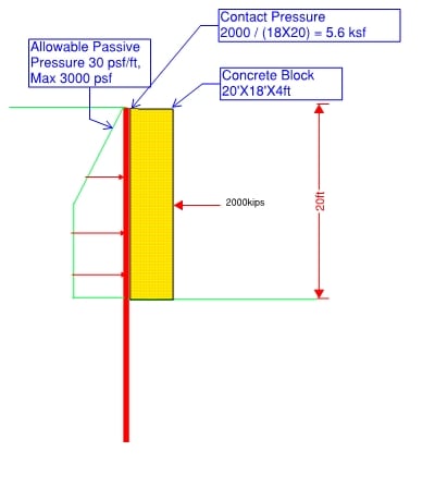
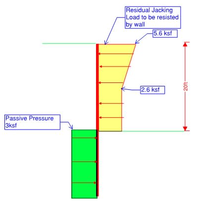
I am working on project that requires a design for jacking and receiving pit. I have no problem designing the retaining wall to resist the active load and reach bottom of the pit. The problem is the jacking load is 2,000 kips. The maximum concrete block we can install is 18ft X 20ft and the maximum passive pressure that the geotech has recommended is 3000 psf max. When you do the math there is 2.6 ksf (2000kip/18X20 - 3 ksf)of pressure remains to be resisted by retaining wall. The way I design it, I use LPILE and distributed load to come up with a CIDH design. The problem is the CIDH is like 4ft DIA. @ 5 ft OC. and even with maximum reinforcement the deflection is excessive. Any recommendation on how to design jacking pit with such a huge load?
 
Replies continue below

Recommended for you

Have you looked at installing anchors in the inclined direction toward the load? Might work better than using passive resistance of a block of concrete or maybe part of its construction.
 
Can you clarify on what you mean by anchors? I originally though of using tieback but they can't work on compression. Are you talking about installing micropiles behind the wall on grade?
 
My old mind has not brought up the correct name for these. A continuous flight hollow stem auger is run into a zone of soil say 30 feet at an angle of say 45 degrees to vertical. Inside the hollow auger stem a grout is pumped down to the tip while the auger is withdrawn, bu leaving in place a steel rod that comes out at the surface to then be pulled on as an anchor. One could use other methods to get that anchorage down there at the tip zone of the tie-back. some might leave the lower end of the auger in place. The inclination angle can be varied but one does no want the zone affected to do much wrong direction pulling on the item being installed I need to add the thing is installed in the direction of the item being pushed, . You make use of the horizontal resistance of this inclined rod being pulled. Another point. If your reaction block is tied to the of this on the side of the work, that may be just enough more resistance that you need.
Another add, hopefully better grammar. You don't need just one, Several can be flayed out under the thing being pushed.
 
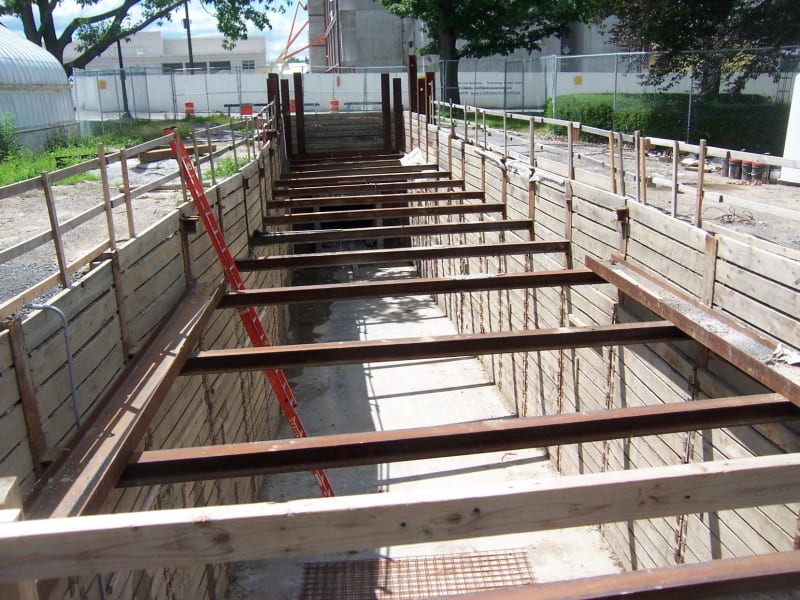
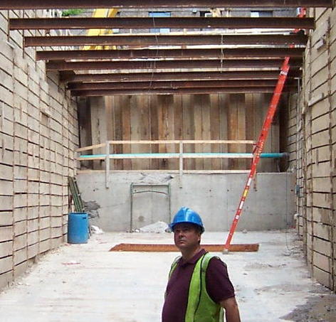
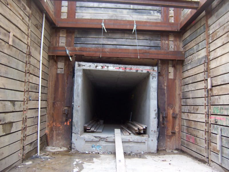
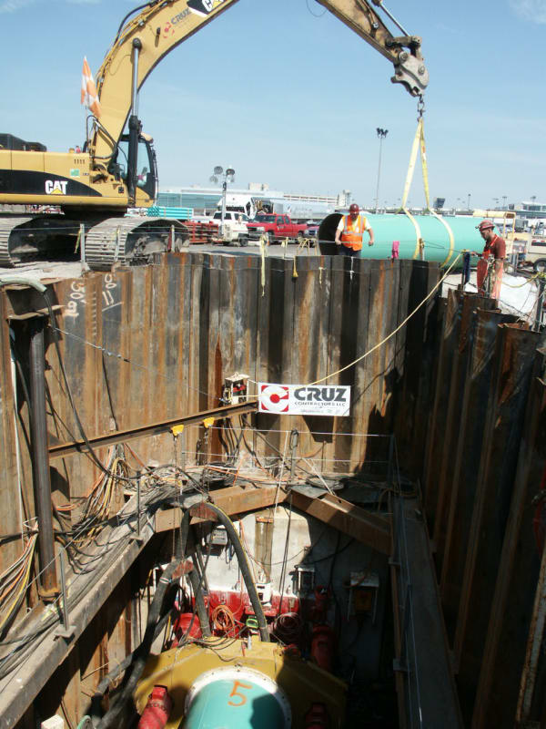
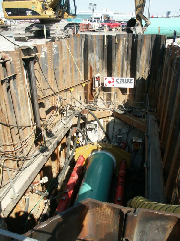
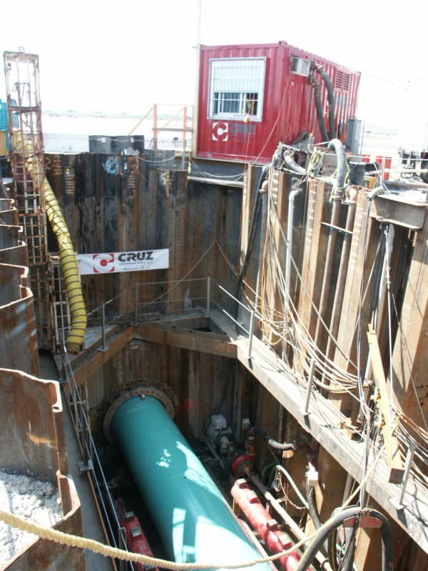
babibibak, I designed a jacking pit for pushing a C-I-P concrete pedestrian tunnel under an active road at an Ivy league University. The jacking force was 2,500 kips. The jacking pit was 120' long by 21' wide by 21' deep. Three of the pit's sides were soldier beams with timber lagging with steel cross braces between opposite soldier beams. For the jacking block end of the pit, I designed a double thick, end wall of PZ27 SSP. In front of the SSP end wall, I designed a reinforced concrete jacking block that was 21' wide by 10' high by 4' thick. The bottom of the concrete block was buried about 2 feet below a poured concrete slab upon which the tunnel was constructed prior to jacking. The tunnel was pushed across the top of the greased-up slab. In front of the concrete block, I designed a double layer of 33" x 66" x 1.25" thick steel plates to distribute the force of the jack pistons to the concrete block. As an extra stiffening measure, the contractor added 2 each, HP12x74 soldier beams behind the SSP end wall (he was worried!). The pit and jacking block worked fine. Here are a few photos:

100_2593_xqxr3i.jpg


100_2564_fnfeuz.jpg


100_2558_2_euggmi.jpg


100_2560_ejakxr.jpg


Thanks for responses. Two questions:

1. Could you please elaborate the double thick wall? I have designed many sheet pile wall but never double thick. Could you please give me reference or explanation?
2. The contact pressure behind the block is almost 12 ksf, did you design the double thick wall for such a huge load? did you take into account the passive pressure? What was the embedment?
 
A question for geotechnical engineers, what is the permissible soil pressure under the concrete block?

j_x5ffm2.png
 
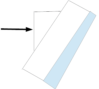
Here is how I see the forces to design the wall. As I said the residual force after I deduct the allowable passive pressure is huge. Even 4 ft CIDH @ 5ft O.C. give me significant deflection (14 in.). I don't know how a sheet pile can resist this load.

1_qxpdes.jpg


2_q6mypt.jpg
 
Can you reach out to your geotechnical engineer, see what his opinion on the concrete block lay on an inclined ground. I wonder if the earth pressure will increase significantly, and settlement become less a problem.
 
babibibak, the double SSP is just one wall of SSP driven as close as possible to the other with little to no space between each line of SSP. S = 30.2 in[sup]3[/sup]/lf x 2 each = 60.4 in[sup]3[/sup]/lf. My SSP was 30' long. I designed for both a triangular and a trapezoidal passive pressure distribution behind the SSP. The maximum trapezoidal pressure magnitude that I used was 6.25 ksf. 2500 kips / 20' long wall = 125 klf. The flat portion of the trapezoid was 10' to match the height of the concrete block. I assumed 10' sloped pressure above and below the flat portion. Therefore the magnitude of the trapezoid was P = 125 klf / ((10' + 10')/2) + 10' = 6.25 ksf.
When I checked the required depth of the SSP to provide the passive resistance (with a FS = 1.5), I needed a 23' long SSP . I used 30' long SSP.
I checked the bending moment of the SSP for the trapezoid pressure distribution and the theoretical triangular pressure distribution.
I used a Coulomb passive earth pressure coefficient with wall friction = 0.5Phi.

I don't think you will find this method in any text book. But it worked fine for the 2,500 kip jacking load.

 
retired13 This is an state project and the change in passive requires act of congress.

PEinc Thanks for the explanation. The soil I am dealing with is a cohesive soil and the maximum allowable passive to resist jacking is 3000 psf.I have a hard time understanding how the 6.25 ksf of load can be resisted by only two layer of sheet pile and 30 ft of embedment. Can you comment on my graphs and share your opinion?
 
Can you utilize cohesion?
 
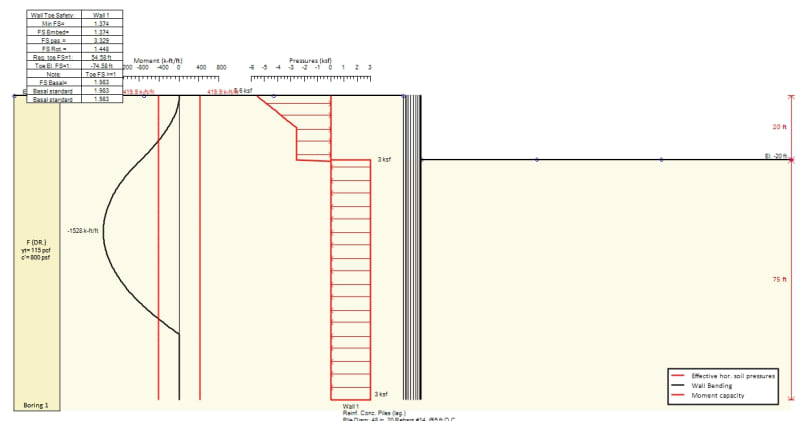
The geotech report specifically says use maximum 3000 psf of passive to resist jacking load. Below is the design. The moment is 1530 kip-ft/ft and embedment is 75 ft. Is there something I am missing?

3_fyutav.jpg
 
Get a new Geotech. Geotechs are too often against taking ANY risks. Their recommended numbers are too often padded for conservatism. Calculate your own passive resistance. Use reasonable soil properties. My soil properties weren't much different from yours if you used drained properties where c = 0 and Phi = about 32 degrees (check your PI to get an approximate drained Phi angle) Don't analyze this as a wall. Look at it like a deadman. I used drained conditions with unit wt. = 125, c = o, Phi = 32 degrees, and delta = 16 degrees. Don't use a Rankine passive earth pressure coefficient. Check the 3,000 psf maximum passive resistance. p[sub]p[/sub] = gamma x K[sub]p[/sub] x D = 3000 = 115 x K[sub]p[/sub] x 20'. Therefore, K[sub]p[/sub] = 1.3. What safety factor is the Geotech applying to the K[sub]p[/sub]? Is this soil like toothpaste? Get rid of the safety factor on K[sub]p[/sub]. Put the safety factor on your jacking load (I hope there isn't already a FS on the 2000 kip load and on the K[sub]p[/sub]). Find the embedment depth you need.

 
Dumb question from OG to PEinc. Assuming the design didn't do what you expected and movement of the reaction block had to be corrected some how. Were there contingency plans to add more resistance? If so what were they?
 
OG, actually, I never even considered a contingency plan. However, if the jacking reaction block did start to move backward, there are several things I could have done AFTER stopping the tunnel jacking. First, the cheapest and fastest fix would have been to place more overburden soil behind the end wall in order to increase the passive resistance. Second, I could have installed some more driven or drilled-in soldier beams or SSP behind the end wall. Third, I could have installed some more SSP in front of the concrete reaction block. Fourth, I could have designed some battered, compression piles and a wale for behind the SSP wall.

What I thought was funny at the time was when the project's reviewing engineer worried that the 2,500 kip jacking force was going to damage a building that was about 100 feet directly behind the reaction block.

 
Nice reply. My thought was similar as to the passive resistance with a load there. So where was the earth stored from the excavation for jacking pit?
 
OG, the portion of the tunnel that got jacked was built in the long sheeted and cross-braced trench. The jacked tunnel was built on a down sloping, greased, concrete slab to help reduce friction. The tunnel was then jacked under the road (reportedly to within a half inch of its planned final location). After the tunnel was jacked, the end wall with the concrete block, SSP, and 2 soldier beams was removed and the sheeted trench was extended back to the building (for which I had to design pit underpinning and needle beam underpinning). Then, about 220 LF of C-I-P concrete pedestrian tunnel was built from the end of the jacked section back to the building that was behind the jacking reaction block. The surplus excavated soil was trucked off site, keeping just enough to backfill the tunnel in the trench.

 
babibibak, just so you don't think that I was lucky that the above, Ivy League, jacking pit and reaction blocked worked, I also designed two more, internally braced SSP jacking pits in predominately soft organic silt at Philadelphia International Airport for jacking 60" diameter casing pipes under a paved runway and a taxiway. I used the same design method as I described for the above Ivy League university project. Pit #1 was 37.5'L x 20.83'W x 20'D with PZC 18 sheets, 36' long. The design jacking force was 714 kips including a safety factor of 2. The Pit #1 end wall was a single SSP wall. Pit #2 was 36.75'L x 18.37'W x 26.5'D with NZ 26 SSP, 50'long. The design jacking force was 1970 kips including a FS = 2. The Pit #2 end wall was a double SSP wall. Both pits, supported 0' to 5' of silt fill soil over deep silt with N = 1 or 2 to mostly WOH. Ground water was assumed to be 5' below original grade, the top of the SSP walls. For Pit #1 the reinforced concrete reaction block was 20.83'L x 10'H x 3'T. For Pit#2, the concrete block was 18.37'L x 10'H x 3'T. For the soils, I used 115 pcf saturated, 53 pcf buoyant, 26 degree Phi, and 13 degrees wall friction.These pits worked fine also.

PICT2210_kqvvsm.jpg


PICT2204_riurxi.jpg


PICT2215_qsz2gt.jpg


PEinc Thank you so much for sharing these incredible photos from projects you have designed. I have no doubt that it wasn't luck. I think I figured out what I was missing. The passive pressure width can be twice the width of the retaining wall. Therefore, the resisting force in my case, even with Max. 3 ksf of passive, become 1800 kip. So, there is only 200 kip remaining to be resisted by wall and embedment. Thanks everyone, especially you PEinc, for sharing your opinion.
 
Status
Not open for further replies.

Part and Inventory Search

Sponsor