Continue to Site

Eng-Tips is the largest engineering community on the Internet

Intelligent Work Forums for Engineering Professionals

  • Congratulations Danlap on being selected by the Eng-Tips community for having the most helpful posts in the forums last week. Way to Go!

Jamb Stud Trib Width and CFS Designer 1

Status
Not open for further replies.

Revv

Structural
Aug 23, 2021
87
Hey guys,

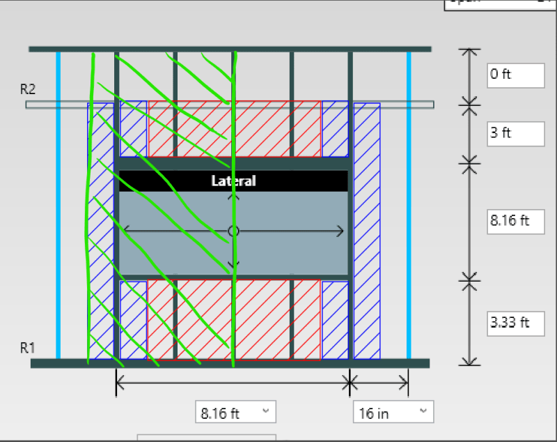
So my understanding is a jamb stud would have the same lateral trib width as a normal stud unless you have a stud over/under the opening closer to it than normal spacing. When I run Simpson CFS designer, it seems to not add that trib width over the opening as if there is a stud immediately adjacent to it above/below the opening.

Anyone have any ideas why it's running like this? Image attached for reference
 
Replies continue below

Recommended for you

Hopefully someone else can answer about that specific program, but I think the out-of-plane loading would be more like this:

Screenshot_2023-01-18_120810_aqqweu.png


The reasoning is that your header/sill is connected to the jamb. Those elements are transferring the out-of-plane loading. You could tweak it a bit and calculate the specific load from the header and sill, but this way is conservative.
 
It's dumping that load into the header and sill, and putting those as point loads onto the jamb.
 
Ah that's right. Agreed with phamENG, it might be doing that. So ignore my method if the program is already considering the header/sill.
 
@phameng exactly but isn't that technically incorrect? It's assuming that either A. it's spanning vertically or B. It's got a stud on each edge of the opening. This would make a difference load wise becasue if it's doing that half of the load never makes it into the jamb(because it goes to the "ground" or the "top")

@ milkshakelake and right but just focusing on the small section in my image. Like Pham said it seems like it's assuming it's spanning vertically.
 
Whether or not it's correct is up to you - what size is the window? How does the window frame transfer load? You need to decide if the load goes to the head/sill only, the jambs only, 2-ways, or a clear opening that transfers no lateral load.

Screenshot_2023-01-18_123725_yhwetm.png
 
@phameng I think my image may be a little misleading so I apologize. I am specifically talking about the trib of the jamb above the opening and below the opening, not in the opening.
 
Honestly, I've done thousands of these by hand and with a spreadsheet and have checked the results with a beam program. I just use (width of window + 16")/2 for trib. for the jamb design and it basically comes out the same as using the head/sill point loads. For the head and sill, I would design for worst case load.
 
@XR250 when I think about load path there is some load missing if we span the panels/sehathing above/below the window vertically instead horizontally
 
Revv - not sure exactly what your concern is, but I just validated the program quickly.

In the opening screen, click on the jambs so they're highlighted. Then right click and send them to beam view. There you can see what the program is using for loading. It uses a uniform load rather than multiple partial span uniform loads. Not sure exactly how it comes up with it, but a quick check shows that the uniform load vs. 3 partial uniform loads of different intensities is accurate to within 5% and the reactions are slightly conservative.
 
The way I mentioned is the same as XR250. It works and isn't much different from point loading. Also have done hundreds of calcs this way.

About the studs above/below the window, it's true that you can consider half the out-of-plane forces to go to your floor diaphragm.
 
My understanding of the OP's problem:

The jamb studs are full height studs and should be loaded by 0.6W*(16") below the sill, 0.6W*(16") above the header, and 0.6W*(8") between them. But CFSDesigner isn't doing that.

I just did a quick check and it's applying 0.67(0.6W*(16")) to the entire thing. So it's just "smoothing it out"
 
@phameng yes exactly. Thank you for the time you've already spent on this but plesae humor me for one last question. So, by the numbers you're showing there, isn't the load LESS than it would be otherwise(assuming the opening isn't taking up most of the span)? Therefore, it's non-conservative? Or are you trying to say that's negligible?
 
Okay. I see it now. Sorry. Had to run a few different arrangements. You're absolutely right...it's ignoring the tributary area over and below the opening and only giving you a load of W*S/2 where S is the spacing.

I think, for most opening types, this wouldn't be an issue. Once you add in reactions from the head and sill and/or 4-way load distribution the jamb will be capable. For openings with no fill, you may run into issues if you have a very small opening, but that's counteracted by the fact that you'd never make your jamb stud smaller than typical wall studs.

So if you feel the need to modify it, you can in the beam view option, but it'll typically come out in the wash.
 
Are the header and sill reactions to the jamb based on a uniform load along the full width of the opening rather than point loads at each of the interior studs? If so, I suspect you're not really losing any tributary area in a practical sense, it's just getting distributed a bit differently. So rather than analyze the jamb for the small strips of partial uninform loads drawn in blue on your sketch, half of that area is brought down/up to the header/sill and then delivered to the jamb as a point load. While not technically exact, this is consistent with the general tributary area method of design where you're not tracking the reaction of each individual joist or stud directly.
 
XR250 said:
I just use (width of window + 16")/2 for trib. for the jamb design

Agree. It comes out much the same. Hence a double or triple stud at wider openings.
 
Status
Not open for further replies.

Part and Inventory Search

Sponsor