Continue to Site

Eng-Tips is the largest engineering community on the Internet

Intelligent Work Forums for Engineering Professionals

  • Congratulations IDS on being selected by the Eng-Tips community for having the most helpful posts in the forums last week. Way to Go!

Job keeps getting aborted? 1

Status
Not open for further replies.

OJM

Civil/Environmental
Dec 15, 2016
33
Hi,

I'm trying to model a reinforced concrete slab with reinforcing bar in the base of the slab and I want to find the failure mode of it.

Along 3 edges it is pinned, along 1edge it is fixed and along the other it is free.

I'm doing a General static step.

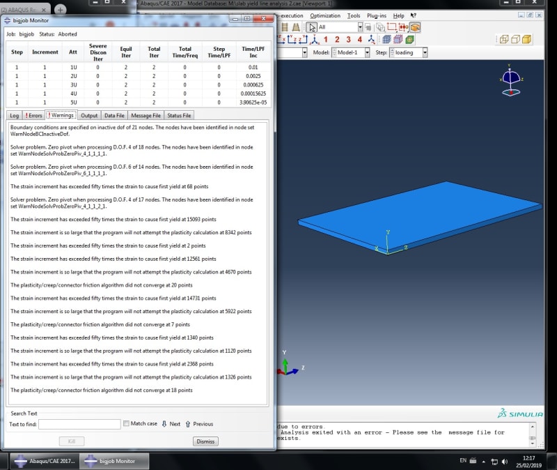
However when I run the job, everything seems to be fine except the step time seems strange.
Abaqus_help_lnyyds.jpg


Please find Abaqus File attached.......

Very grateful for any help

 
Replies continue below

Recommended for you

It means that the solver can't reach convergence. There can be many different reason but usually it happens in case of nonlinear analyses, especially with contact. I can't open your file now so could you tell me - how did you model the reinforcing bar (beam/solid/stringer) and interaction between it and slab ?
 
I modeled the rebar with a wire element and assigned it a circular section, I wasn't exactly sure about the proper way to do this. I set the interaction between the slab and rebar as an embedded region, also the horizontal and vertical spanning rebar were overlapping (on the same Z coordinate) could this be a problem?


also when I went to run it apparently I needed to set orientation? I'm not sure what this means, but I set it to (0,0,-1) or something like this... I hope that ins't to cause of the problem.

Thanks
 
Also I left one of the edges without any boundary conditions.
 
1) Your choice of embedded region constraint is good. I properly defined it shouldn't cause any problems.

2) I suggest fixing this overlapping even though it's probably not the reason for non-convergence. Connect beam parts in such way that they meet at common node where they are connected.

3) Orientation must be set for beam elements (usually default one is sufficient) so that section forces and moments can be calculated. You can display the beam orientation in viewport at any time. If you miss that definition, another error will appear but this is probably not the case here.

4) Rigid body motions (underconstrained model) are very common reason of this error. Make sure that all these motions are constrained. For solid elements you need to fix translations in 3 directions while for beam elements you should also consider rotations.
 
Thanks for your reply, it is greatly appreciated.

I have gone through your points, I have separated the layer of rebar from each other, and still have the same problem. Not quite sure what you mean but connect beam parts at a node, because they shouldn't meet (because they are spaced equally apart from each other).

SO the orientation of the rebar shouldn't be a problem.. as the profiles are circular so their properties are the same when axially rotated in any way.

I have no rigid body constraints, so i'm not too sure what you mean by that. Also how do you fix translations in three directions? Not seen this done on similar tutorials.

Thanks again


I thought that your beams are crossing but now I see that they only have common z coordinate so they are one above the other. That won't cause any problems.

Orientation must be assigned for the solver to start but if it's done then it actually doesn't matter how the directions are set.

Rigid body constraints are something else. I was talking about rigid body motions which occur when the body is not fully constraint and thus can move in some direction(s) without deformation (it can "fly away" or rotate freely). Your boundary conditions must be set in such manner that no free movement is possible. You can either fix one boundary in all 3 directions or apply 3 separate constraints which together can hold the body in one place.
 
The job shows numerical singularities, because the beam elements still have their rotational DOF. Restrain them or just activate stabilization in the step option.
 
3 of the 4 sides of my slab have boundary conditions (one of which is ENCASTRE i.e. fixed in all directions), and the other is left as a free end, so you're saying this needs a boundary condition also? or are you talking about the rebar (beams)? I have not set and boundary conditions for the rebar because I do not know how to.

Do you mean automatic stabilisations? there are three options, specify dissipated energy fraction, specify damping factor and use damping factor from previous step. Sorry for my lack of understanding but which would I choose? and what values would I choose?
 
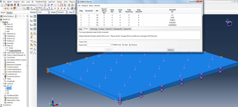
I have tried to make a fresh model and this is what happens

Abaqus_help_2_l4epbf.jpg
 
Zero pivot error - clear sign that something is underconstrained (you can view these nodes as suggested in the error message). One encastre for the slab is enough so it must be about the beams. You should fix them like you would if they were analyzed without the slab. If you can’t select them because they are inside the slab then just hide the slab using diplay group options.

Also you can perform eigenfrequency extraction analysis. Rigid body modes will appear at near zero frequency and you will be able to see which part of the model is underconstrained.
 
I fixed the rebar on the ends and it hard finally worked!!!

Thank you for your help! very much appreciated
 
Status
Not open for further replies.

Part and Inventory Search

Sponsor